Sleeveless solenoid for a linear actuator

a linear actuator and solenoid technology, applied in the direction of valve operating means/release devices, machines/engines, etc., can solve the problems of unpredictable variances in the size and shape of the air gap and in the corresponding response of the armature, limiting the maximum actuating force of the solenoid, and armature may still be unacceptably decentered by gravity. , to achieve the effect of reducing the air gap, reducing the thickness, and increasing the actuating for

Inactive Publication Date: 2005-10-18
DELPHI TECH INC
View PDF24 Cites 13 Cited by
  • Summary
  • Abstract
  • Description
  • Claims
  • Application Information

AI Technical Summary

Benefits of technology

[0007]The present invention is directed to an improved solenoid for providing linear actuation. The outer polepiece of the solenoid is provided with an axial, self-lubricated, non-magnetic journal bearing for supporting an actuating shaft extending coaxially from the solenoid armature. Preferably, the radial tolerance between the diameters of the bearing inner bore and the shaft is as small as in practically possible without inducing significant drag of the shaft in the bearing. This permits reduction of the air gap between the armature and the polepieces to a minimal thickness. Preferably, the armature is axially tapered slightly to avoid contact with the polepieces as a result of residual tolerances between the bearing and shaft. A significant increase in actuating force is realized in comparison with a prior art solenoid actuator.

Problems solved by technology

Further, the armature is not spontaneously centered in the bore, and non-axial magnetic vectors within the bore destabilize centering of the armature, resulting in unpredictable variances in the size and shape of the air gap and in the corresponding response of the armature.
Such a sleeve can reduce the centering problem but in itself still contributes to the thickness of the non-magnetic gap between the armature and the polepieces, thus limiting the maximum actuating force of the solenoid.
Further, because of necessary tolerances between the sleeve and the armature and between the sleeve and the polepieces, the armature may still be unacceptably decentered by gravity if the actuator is used in orientations wherein the actuator axis is inclined more than about 30° from vertical.
Thus, prior art solenoid actuators can impose serious engineering design restrictions in their use.

Method used


Image

  • Sleeveless solenoid for a linear actuator
  • Sleeveless solenoid for a linear actuator
  • Sleeveless solenoid for a linear actuator

Examples


Embodiment Construction

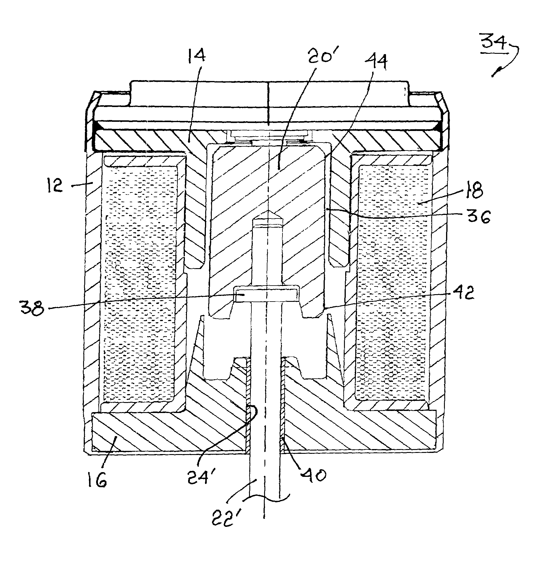
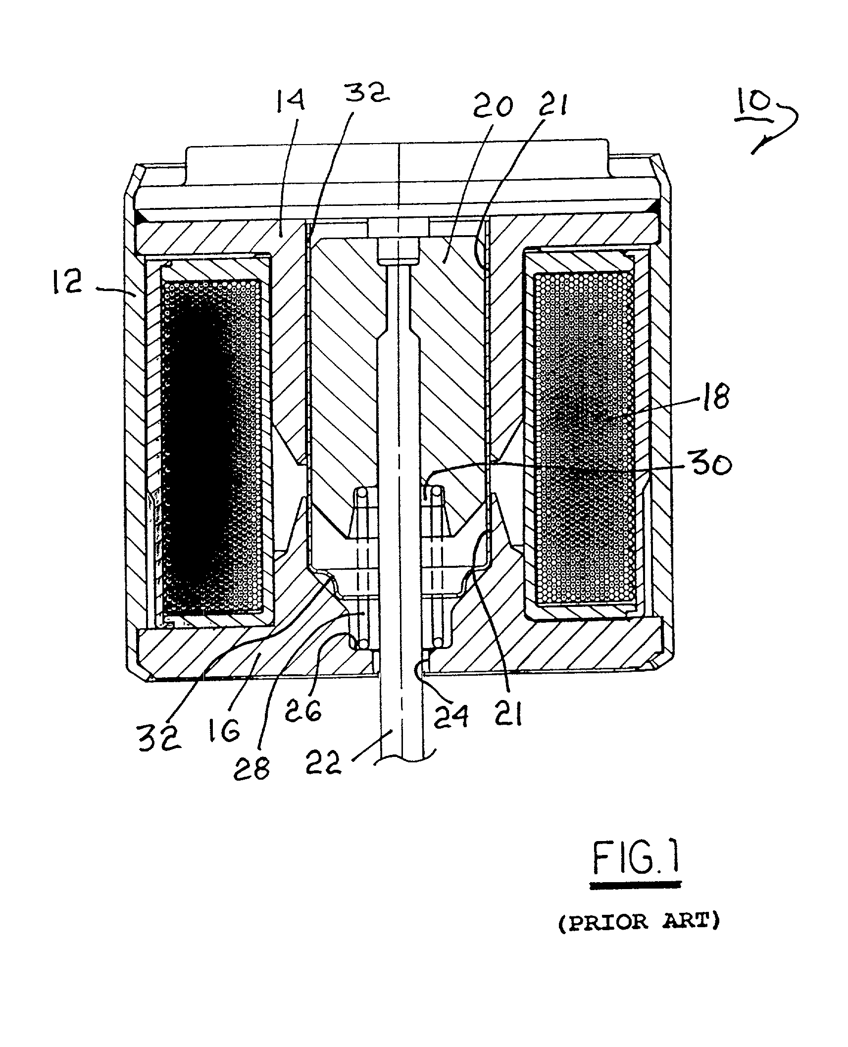
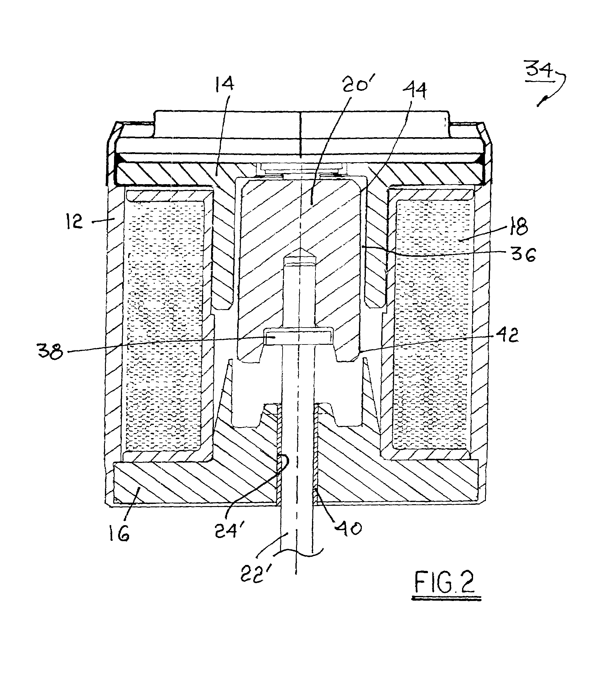
[0013]The benefits afforded by the present invention will become more readily apparent by first considering a prior art solenoid actuator. Referring to FIG. 1, a prior art actuator 10 includes a housing 12 containing first and second pole pieces 14, 16, respectively, and a plurality of windings 18 about the polepieces. A ferromagnetic armature 20 is slidably disposed within a stepped first axial bore 21 in the pole pieces. An actuating shaft 22 is axially disposed and retained within armature 20 and extends from housing 12 via a second axial bore 24 in polepiece 16 for connection to work. Step 26 in bore 21 receives a coil spring 28 disposed in compression between step 26 and a well 30 in armature 20 for biasing the armature into the solenoid. A generally cylindrical non-magnetic sleeve 32 surrounds armature 20 and spring 28 for slidably guiding and centering the armature axially of the polepieces. Typically, the sleeve is formed of a non-galling non-ferromagnetic material such as s...


PUM

PropertyMeasurementUnit
electromagnetic displacementaaaaaaaaaa
axial lengthaaaaaaaaaa
diameteraaaaaaaaaa

Abstract

An improved electric solenoid for providing linear mechanical actuation. The outer polepiece of the solenoid is provided with an axial, self-lubricated, non-magnetic bearing for closely supporting and centering an actuating shaft extending coaxially from the solenoid armature. Preferably, the radial tolerance between the diameters of the bearing inner bore and the shaft is as small as in practically possible without inducing drag of the shaft in the bearing, permitting reduction of the air gap between the armature and the polepieces to a minimal thickness. Preferably, the armature is axially tapered to avoid contact of the armature with the polepieces as a result of residual tolerances between the bearing and shaft. A significant increase in actuating force is realized in comparison with a prior art solenoid, and the improved solenoid may be used in any desired orientation.

Description

TECHNICAL FIELD[0001]The present invention relates to electric solenoids as used in mechanical linear actuators; more particularly, to such solenoids intended for continuous, controlled linear travel between two extremes; and most particularly, to such solenoids as may be required to operate without regard to orientation.BACKGROUND OF THE INVENTION[0002]Electric solenoids are well known in electrical engineering and are widely used as actuating components in electromechanical actuators. A typical electric solenoid consists of a plurality of windings of an electric conductor about north and south polepieces. When current is passed through the windings, a characteristic toroidal magnetic field is produced having field lines at the axis which are parallel to the axis. A ferromagnetic armature is slidably disposed in an axial bore in the polepieces. An axial force is exerted by the magnetic field on the armature which tends to displace the armature axially. The strength of such force ca...

Claims


Application Information

Patent Timeline
Patent Type & Authority Patents(United States)
IPC IPC(8): F02M25/07H01F7/08H01F7/16
CPCF02M25/0772F02M25/0789H01F7/1607Y02T10/121F02M26/53F02M26/67
Inventor BIRCANN, RAUL A.PALMER, DWIGHT O.
Owner DELPHI TECH INC
Why Eureka
Try Eureka