Object preparation device and particle beam device with an object preparation device and method for operating the particle beam device

a technology of object preparation and preparation device, which is applied in the direction of material analysis using wave/particle radiation, instruments, nuclear engineering, etc., can solve the problems of not always ensuring the in particular the precise removal of the layer of the object, and inability to place the microtome with the specimen stage or the stand, etc., to achieve convenient and sufficient positioning of the microtome and good functionality of the microtome

Active Publication Date: 2019-06-11
CARL ZEISS MICROSCOPY GMBH
View PDF20 Cites 0 Cited by
  • Summary
  • Abstract
  • Description
  • Claims
  • Application Information

AI Technical Summary

Benefits of technology

[0016]The system described herein is based on the object of specifying an object preparation device and a particle beam apparatus having an object preparation device, in which a contamination of an area that is exposed by a knife is avoided and which facilitate a sufficient positioning of the microtome and of the object while maintaining a good functionality of the microtome.

Problems solved by technology

The known microtome has a large mass and long adjustment travels of the stand, and so setting a position of the microtome with the specimen stage or the stand is only possible with a great force.
As a result of this, there are inaccuracies when positioning the object, and so the functionality of the microtome, in particular the precise removal of layers of the object, is not always ensured.
However, this is not desired.
What may happen during this movement is that contaminants that have remained stuck to the knife despite the cleaning process fall onto the exposed area and, as a result thereof, falsify an imaging of the exposed area.
Further, on account of the swivelable stand, the known microtome has a great installation height, and so a positioning of the known microtome with the adjustment travels of the specimen stage of the SEM is not always possible to a sufficient extent.

Method used


Image

  • Object preparation device and particle beam device with an object preparation device and method for operating the particle beam device
  • Object preparation device and particle beam device with an object preparation device and method for operating the particle beam device
  • Object preparation device and particle beam device with an object preparation device and method for operating the particle beam device

Examples


Embodiment Construction

[0078]Some embodiments of the system described herein are now explained in more detail by means of particle beam apparatuses in the form of an SEM and in the form of a combination apparatus, which has an electron beam column and an ion beam column. Reference is explicitly made to the fact that the system described herein may be used in any particle beam apparatus, in particular in every electron beam apparatus and / or in every ion beam apparatus.

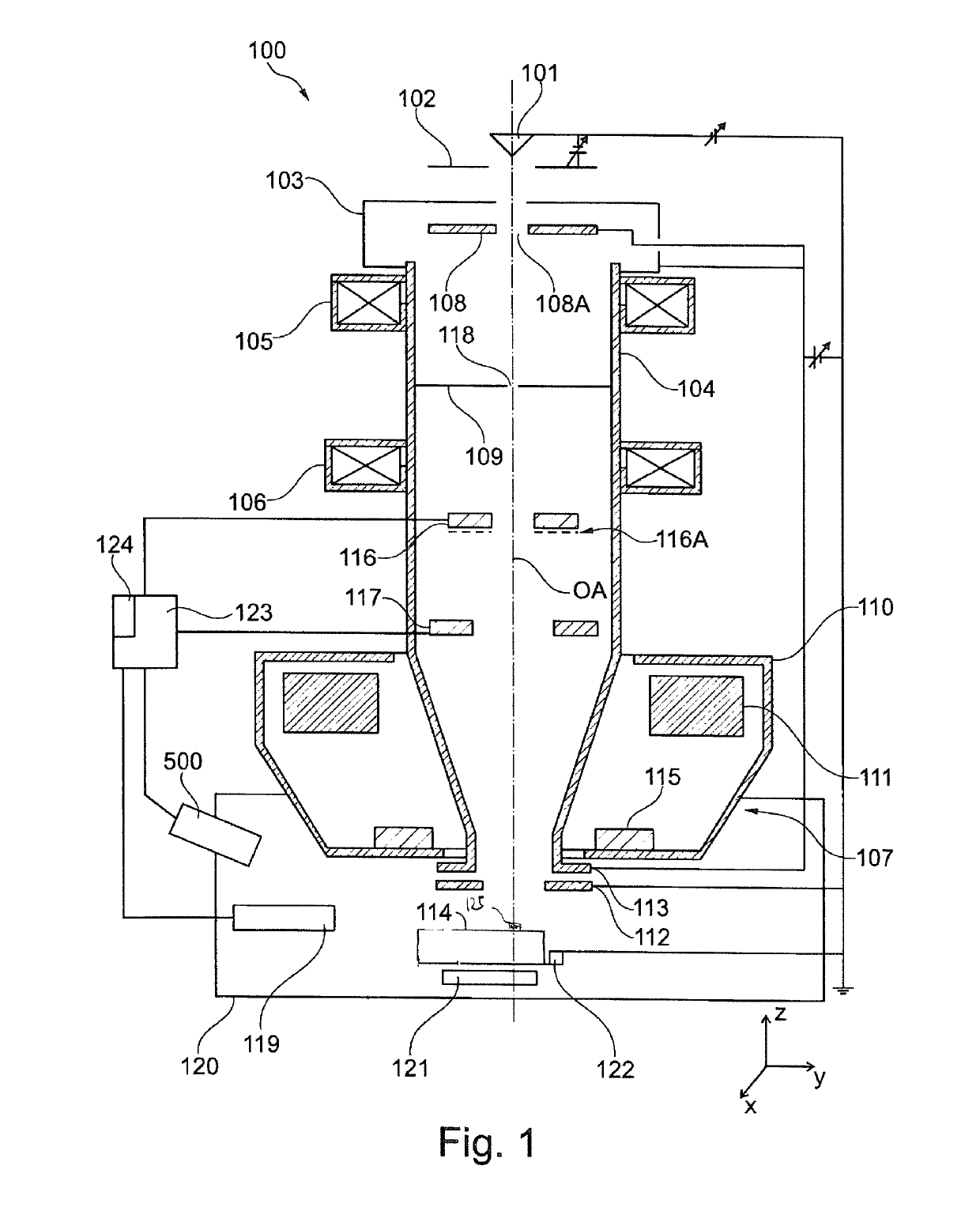
[0079]FIG. 1 shows a schematic illustration of an SEM 100, according to an embodiment of the system described herein. The SEM 100 comprises a first beam generator in the form of an electron source 101, which may be embodied as a cathode. Further, the SEM 100 may be provided with an extraction electrode 102 and with an anode 103, which is placed onto one end of a beam-guiding tube 104 of the SEM 100. By way of example, the electron source 101 is embodied as a thermal field emitter. However, the system described herein is not restricted to such...


PUM

PropertyMeasurementUnit
angleaaaaaaaaaa
angleaaaaaaaaaa
pressuresaaaaaaaaaa

Abstract

An object preparation device for preparing an object in a particle beam apparatus includes at least one cutting device, at least one cutting bevel for cutting the object, where the cutting bevel is arranged at the cutting device, at least one movably embodied object receptacle device having an object receptacle for receiving the object, and at least one drive unit for moving the object receptacle device from a first position of the object receptacle device into a second position of the object receptacle device. The first position of the object receptacle device is an initial position. The second position of the object receptacle device is an analysis and / or processing position of the object receptacle device. An observation axis (OA) extends through the object receptacle when the object receptacle device is arranged at the second position.

Description

TECHNICAL FIELD[0001]The system described herein relates to an object preparation device for preparing an object in a particle beam apparatus, such as an electron beam apparatus and / or an ion beam apparatus. The system described herein moreover relates to a particle beam apparatus having such an object preparation device and to a method for operating the particle beam apparatus.BACKGROUND OF THE INVENTION[0002]Electron beam apparatuses, in particular a scanning electron microscope (also referred to as SEM below) and / or a transmission electron microscope (also referred to as TEM below), are used to examine objects (also referred to as specimens) in order to obtain knowledge in respect of the properties and behaviors of the objects under certain conditions.[0003]In an SEM, an electron beam (also referred to as primary electron beam below) is generated by means of a beam generator and focused on an object to be examined by way of a beam-guiding system. An objective lens is used for foc...

Claims


Application Information

Patent Timeline
Patent Type & Authority Patents(United States)
IPC IPC(8): H01J37/20G21K5/04H01J37/28H01J37/22G01N23/2254H01J37/244H01J37/153G01N23/2252
CPCH01J37/28G01N23/2252G01N23/2254H01J37/153H01J37/20H01J37/244H01J37/222H01J2237/226G01N2223/418H01J2237/20214H01J2237/221G01N1/06G01N1/28G01N2001/065H01J2237/206H01J2237/202H01J2237/1534
Inventor BIBERGER, JOSEFSCHMAUNZ, ANDREASWALTER, GERO
Owner CARL ZEISS MICROSCOPY GMBH
Why Eureka
Try Eureka