A Transformer Winding Deformation Fault Location Detection Method

A transformer winding and fault location technology, which is applied in transformer testing, electric winding testing, electric/magnetic solid deformation measurement, etc., can solve the problem that transformer faults cannot detect winding deformation fault locations, and achieve the effect of preventing power grid accidents

Active Publication Date: 2021-11-02
ELECTRIC POWER RES INST OF GUANGDONG POWER GRID
View PDF4 Cites 0 Cited by
  • Summary
  • Abstract
  • Description
  • Claims
  • Application Information

AI Technical Summary

Problems solved by technology

[0005] The invention provides a transformer winding deformation fault location detection method, which solves the technical problem that the detection of transformer faults in the prior art cannot detect the winding deformation fault location

Method used


Image

  • A Transformer Winding Deformation Fault Location Detection Method
  • A Transformer Winding Deformation Fault Location Detection Method
  • A Transformer Winding Deformation Fault Location Detection Method

Examples


Embodiment 1

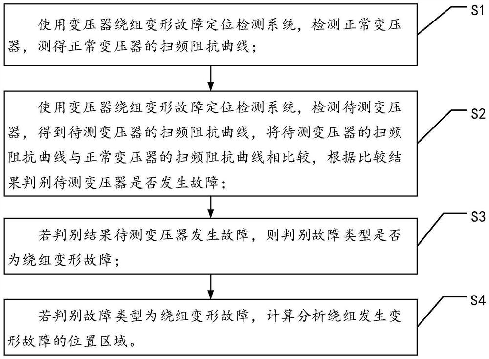
[0041] see figure 1 ,figure 1 It is a method flowchart of a transformer winding deformation fault location detection method provided by an embodiment of the present invention.

[0042] A transformer winding deformation fault location detection method provided by the present invention comprises the following steps:

[0043] Step S1: Short-circuit the winding on one side of the normal transformer, and connect the winding on the other side to the transformer winding deformation fault location detection system, use the transformer winding deformation fault location detection system to detect the normal transformer, and measure the normal transformer in a specific frequency band (10hz-1Mhz) The short-circuit impedance of the normal transformer is drawn according to the frequency change and impedance value;

[0044] Step S2: Use the transformer winding deformation fault location detection system to detect the transformer to be tested, obtain the frequency sweep impedance curve of t...

Embodiment 2

[0063] In this embodiment, it is specifically described how the transformer winding deformation fault location detection system solves the frequency sweep impedance;

[0064] Short-circuit the outgoing line of the high-voltage side or low-voltage side of the transformer, and load the frequency sweep signal at the first end of the non-short-circuit side winding After the signal passes through the winding, the output signal at the end of the winding is obtained by using the grounding resistor R According to the above data, the frequency sweep impedance value of the transformer can be obtained as:

[0065]

[0066] in, To detect the current, ω is the angular frequency of the injected signal; R is the resistance of the transformer; X is the reactance of the transformer.

[0067] Thus, the frequency sweep impedance value can be obtained as:

[0068]

[0069] Since the nameplate value of the transformer is generally represented by impedance voltage, the frequency sweep i...

Embodiment 3

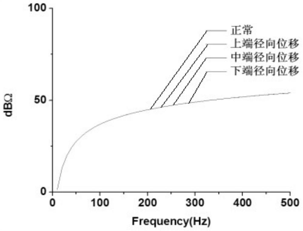
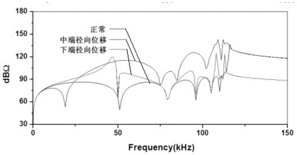
[0092] In this embodiment, when studying the radial displacement fault experiment of the winding, capacitors of 5.8pF, 18.3pF, 35.8pF and 220pF were selected (each grade of capacitance represents different degrees of winding deformation, wherein, 5.8pF: very slight deformation; 18.3pF: slight deformation; 35.8pF: moderate deformation; 220pF: large deformation), connected to the upper, middle and lower ends of the two-phase high-voltage windings of transformers A and B through wires (simulating faults at the upper, middle and lower terminals They are respectively placed in the two-phase 8 cake room, 24 cake room and 39 cake room). Experiments are carried out to obtain the frequency sweep impedance curves of each end and the experimental verification is carried out.

[0093] Such as Figure 4 as shown, Figure 4 It is the frequency sweep impedance curve under the radial displacement fault at the upper end. When the radial displacement of the transformer occurs at the upper end ...


PUM


Abstract

The invention discloses a transformer winding deformation fault location detection method, which is used to solve the technical problem that the transformer fault detection cannot locate the winding deformation fault location. The invention includes the following steps: using a transformer winding deformation fault location detection system to detect the normal transformer and the transformer to be tested, to measure the frequency sweep impedance curves of the normal transformer and the transformer to be tested, to compare the sweep frequency impedance curves of the two, and to compare the results according to the comparison result. Determine whether the transformer under test has a winding deformation fault and calculate and analyze the location area of ​​the winding deformation fault. The invention establishes a transformer winding deformation fault location detection system to connect with the transformer, obtains the frequency sweep impedance curve of the transformer to locate the transformer winding deformation fault, and solves the problem that the prior art cannot locate the position of the transformer winding deformation fault. It is of great significance to prevent power grid accidents.

Description

technical field [0001] The invention relates to the technical field of transformer fault detection, in particular to a transformer winding deformation fault location detection method. Background technique [0002] Transformer is one of the main equipment of the power system, which plays a pivotal role in grid interconnection and power exchange. When the transformer is subjected to short-circuit impact or transportation collision and other factors, the transformer winding may undergo axial or radial dimension changes under the action of electrodynamic or mechanical force, usually characterized by local distortion, bulge or displacement of the winding, which is called winding out of shape. Severe winding deformation will lead to insulation breakdown, resulting in power system accidents and huge economic and social losses. The difficulty of the transformer winding deformation problem is that the winding deformation has the characteristics of concealment and gradual change, an...

Claims


Application Information

Patent Timeline
Patent Type & Authority Patents(China)
IPC IPC(8): G01R27/08G01R27/02G01R31/52G01R31/62G01R31/72G01B7/16
CPCG01B7/16G01B7/18G01R27/02G01R27/08
Inventor 杨贤蔡玲珑孙文星肖祥马志钦周丹靳宇晖周永言刘剑锋向谆潘君镇
Owner ELECTRIC POWER RES INST OF GUANGDONG POWER GRID
Why Eureka
Try Eureka