Sim card mounting structure of mobile phone

a mobile phone and mounting structure technology, applied in transmission, substation equipment, instruments, etc., can solve the problems of high cost of mobile phones, difficult to make the sim card mounting structure inexpensive, lightweight and compact, etc., and achieve the effect of facilitating the mounting operation of the sim card

Inactive Publication Date: 2005-05-10
NEC CORP
View PDF6 Cites 10 Cited by
  • Summary
  • Abstract
  • Description
  • Claims
  • Application Information

AI Technical Summary

Benefits of technology

[0014]The pressing portion may have an opening for confirming a mounting state of the SIM card. That is, a user can confirm the mounting state of the SIM card through the opening.
[0015]As mentioned, according to the present invention, it is possible to provide an inexpensive SIM card mounting structure of a mo...

Problems solved by technology

In such conventional SIM card mounting structure, however, there are problems of complication of the SIM card mounting structure, cost-up of the mobile phone due to provision of suc...

Method used


Image

  • Sim card mounting structure of mobile phone
  • Sim card mounting structure of mobile phone
  • Sim card mounting structure of mobile phone

Examples


Embodiment Construction

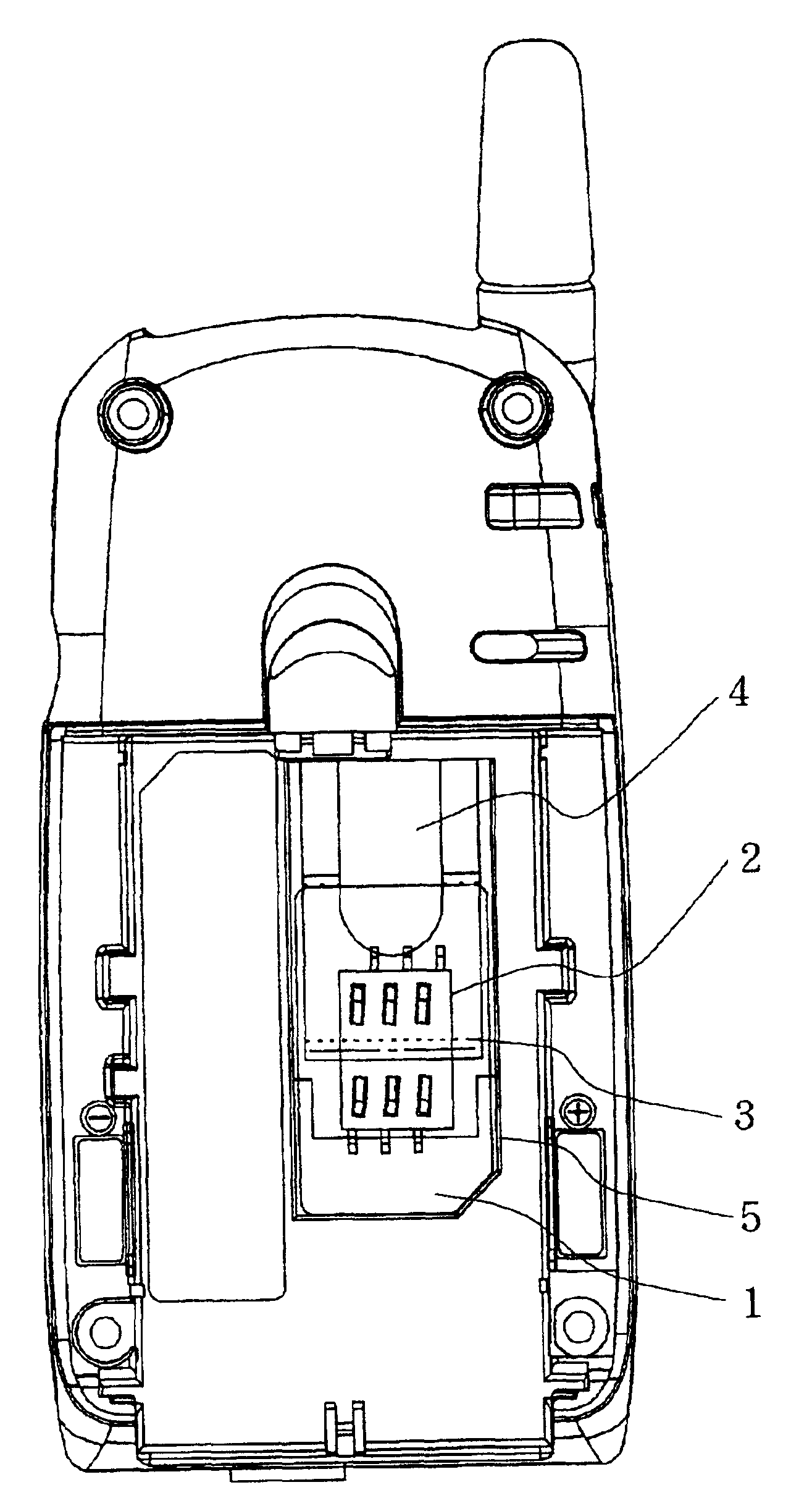
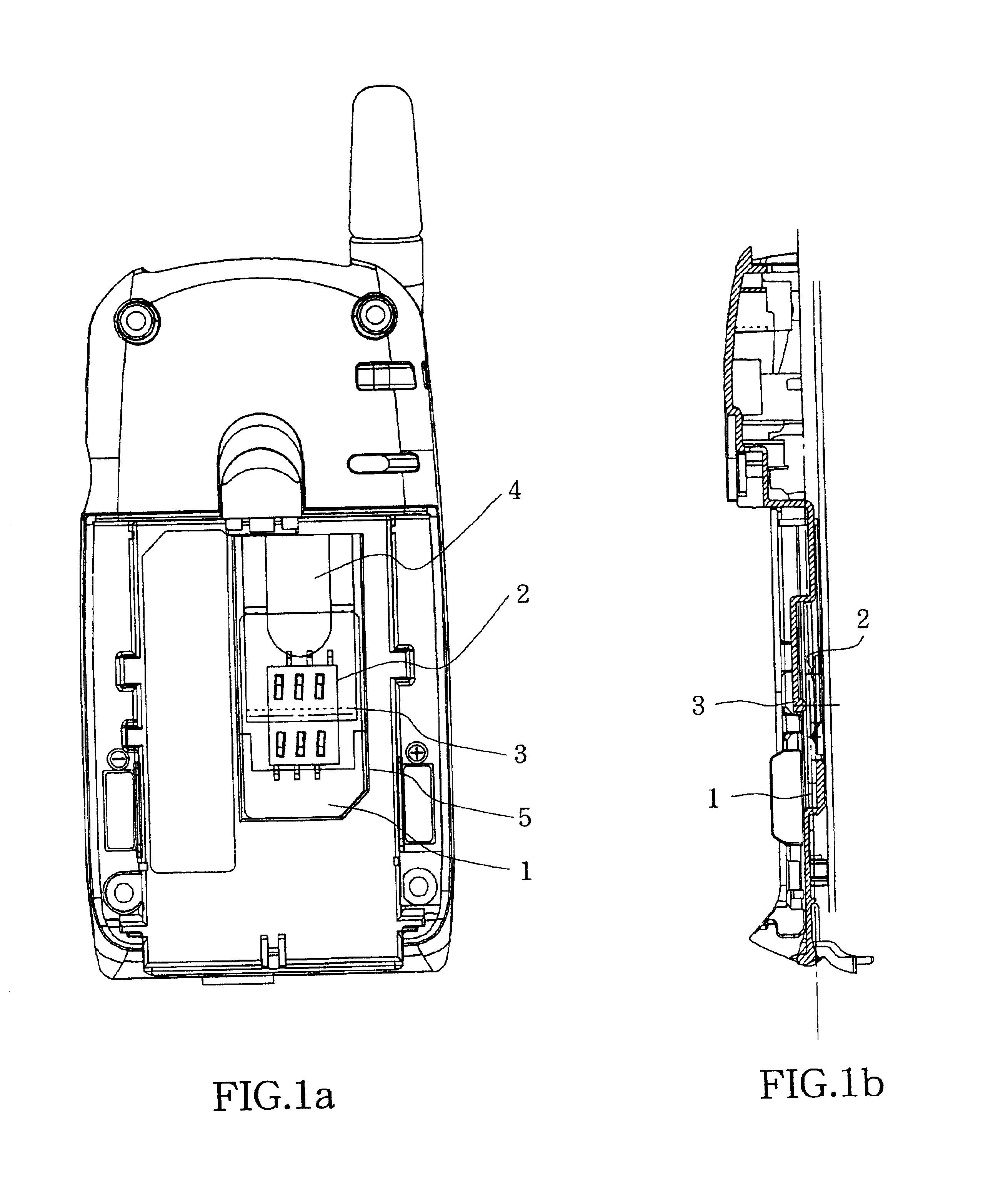
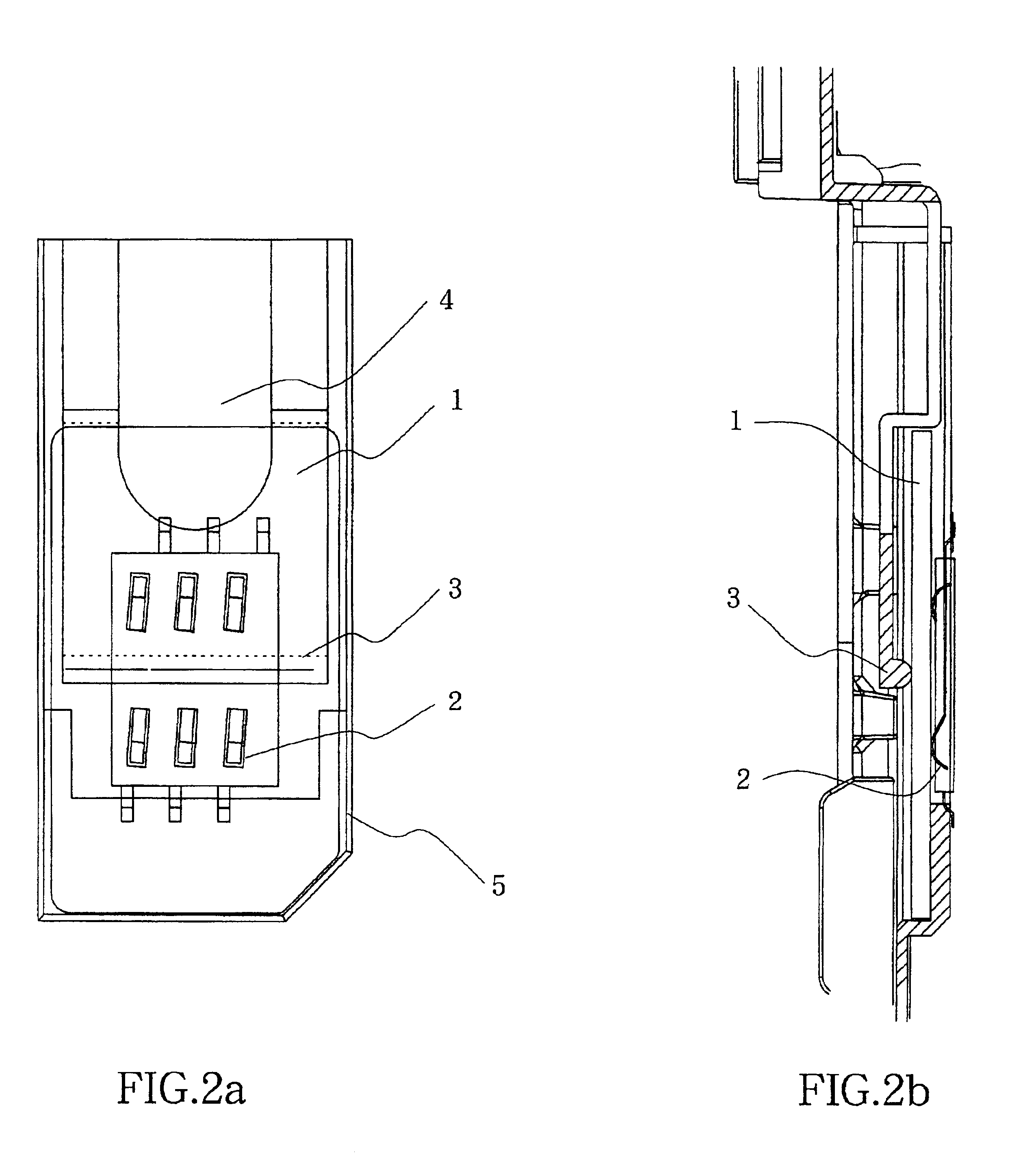
[0026]A SIM card mounting structure of a mobile phone, according to the present invention, is constructed such that a SIM card can be mounted and demounted easily by only a part formed integrally with a front side casing of the mobile phone without necessity of using a separately prepared SIM card mounting part such as the metal lock member 12 shown in FIG. 4A. FIG. 1A and FIG. 1B are a plan view and a cross sectional side view showing a whole construction of a SIM card mounting structure according to a first embodiment of the present invention, respectively, and FIG. 2A and FIG. 2B are an enlarged plan view and an enlarged cross sectional side view showing a main portion of the mobile phone shown in FIG. 1A and FIG. 1B, respectively. In these figures, parts, which are the same as those shown in FIG. 4A and FIG. 4B, are shown without using reference numerals.

[0027]Referring to FIG. 1A and FIG. 1B and FIG. 2A and FIG. 2B, a pressing portion 3 and a SIM card mounting portion 10 of the...


PUM


Abstract

A SIM card mounting structure of a mobile phone includes a SIM card receiving recess 5 provided in a rear surface portion of a front side casing of the mobile phone for fittingly receiving a SIM card 1 therein, a pressing portion 3 formed of an elastic material and having one end integrally formed with the rear surface portion of the front side casing and the other end positioned over the SIM card receiving recess to elastically press the SIM card 1 and electrode terminals 2 for connecting electrodes of the SIM card 1 to a battery. The electrode terminals 2 are formed of an elastic material and arranged on a bottom of the recess 5 in an opposing relation to electrodes of the SIM card 1. The one end of the pressing portion is formed integrally on an end portion of the SIM card receiving recess 5 in a longitudinal direction of the mobile phone such that the pressing portion functions as a longitudinal leaf spring. The pressing portion 3 has a notch 4 for setting elasticity of the pressing portion appropriately and facilitating a handling operation of a SIM card.

Description

BACKGROUND OF THE INVENTION[0001]1. Field of the Invention[0002]The present invention relates to a SIM card mounting structure of a mobile phone.[0003]2. Description of Related Art[0004]FIG. 4A and FIG. 4B are a plan view and a cross sectional side view of a conventional SIM card mounting structure, respectively. In FIG. 4A showing a rear surface of a front side casing of a mobile phone, one end portion of a back side casing (not shown) is rotatably supported by a rotary shaft 11 provided in one end portion of the front side casing so that the back side casing can be lain upon a SIM card mounting portion 10 of the SIM card mounting structure. When a telephone function of the mobile phone is used, the back side casing lain upon the SIM card mounting portion 10 is locked in its position by a locking member 24. The SIM card mounting structure shown in FIG. 4A is in a state where the back side casing is removed and a SIM card is exposed. The term “front side” used in this specification ...

Claims


Application Information

Patent Timeline
IPC IPC(8): G06K7/00H04B1/38G06K17/00H01R13/64H04M1/02
CPCH04B1/3816G06K7/0021H04M1/0202
Inventor SAKAGUCHI, KATSUYASAITO, TOYOSHI
Owner NEC CORP
Why Eureka
Try Eureka