Weed trimmer safety guard

a safety guard and weed trimmer technology, applied in metal working apparatus, agriculture tools and machines, agriculture, etc., can solve the problems of unsightly mess that must be removed at the expense of time and labor, only limited protection against injury, and increase the cutting so as to prevent flexible materials, improve the performance of prior art weed trimmers, and increase the cutting performance

Inactive Publication Date: 2005-05-17
PETERSON MARGARET +1
View PDF22 Cites 21 Cited by
  • Summary
  • Abstract
  • Description
  • Claims
  • Application Information

AI Technical Summary

Benefits of technology

[0009]The present invention provides for an article and method for an improved cutting element cover apparatus that protects both the user of a weed trimmer, and those standing nearby the user of a weed trimmer, from projectiles and debris being distributed to the front and sides or portions of the sides of the weed trimmer while the weed trimmer is being used. A preferred embodiment of the weed trimmer comprises a domed guard structure that encompasses the effective cutting range of a prior art weed trimmer. Alternative embodiments may comprise elements that protect only portions of front, side and rear cutting areas. Embodiments of the invention also allow a user to lift up a cover element to allow close work among obstructions. Embodiments of the present invention also improve the performance of prior art weed trimmers by increasing cutting performance and preventing flexible materials from wrapping about the cutting elements and shafts.

Problems solved by technology

However, there are many disadvantages with the prior art weed trimmers described thus far.
It also offers only limited protection against injury from encounters with the cutting element 18 as it is cutting rapidly about the base of the weed trimmer.
Anyone who encounters the rotating cutting element from the side or the front of the weed trimmer may be injured by the rapidly moving cutting element 18.
This problem is particularly undesirable where one is trimming vegetation by a lake and does not wish to have vegetation and debris cast into the lake, creating an unsightly mess that must be removed at an expense of time and labor.
Typical prior art weed trimmers also have problems cutting tall flexible vegetations, such as tall thick grasses, which tend to wrap around the shaft area immediately above the rotating spool of the cutting element cord and may even stall the weed trimmer.

Method used


Image

  • Weed trimmer safety guard
  • Weed trimmer safety guard
  • Weed trimmer safety guard

Examples


embodiment 50

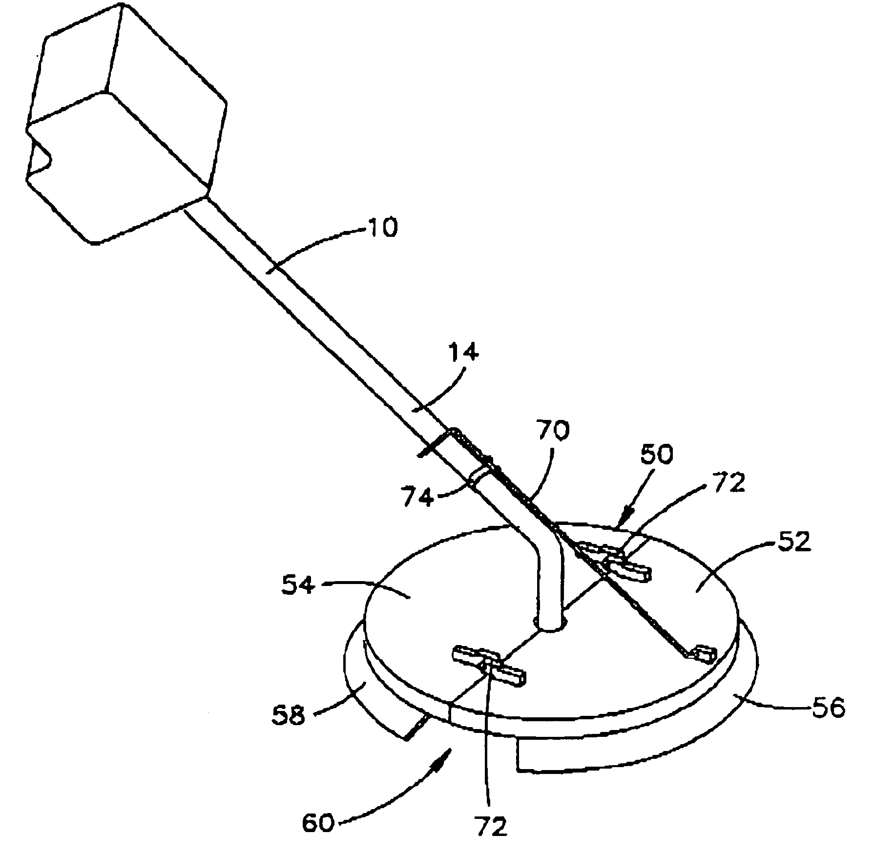
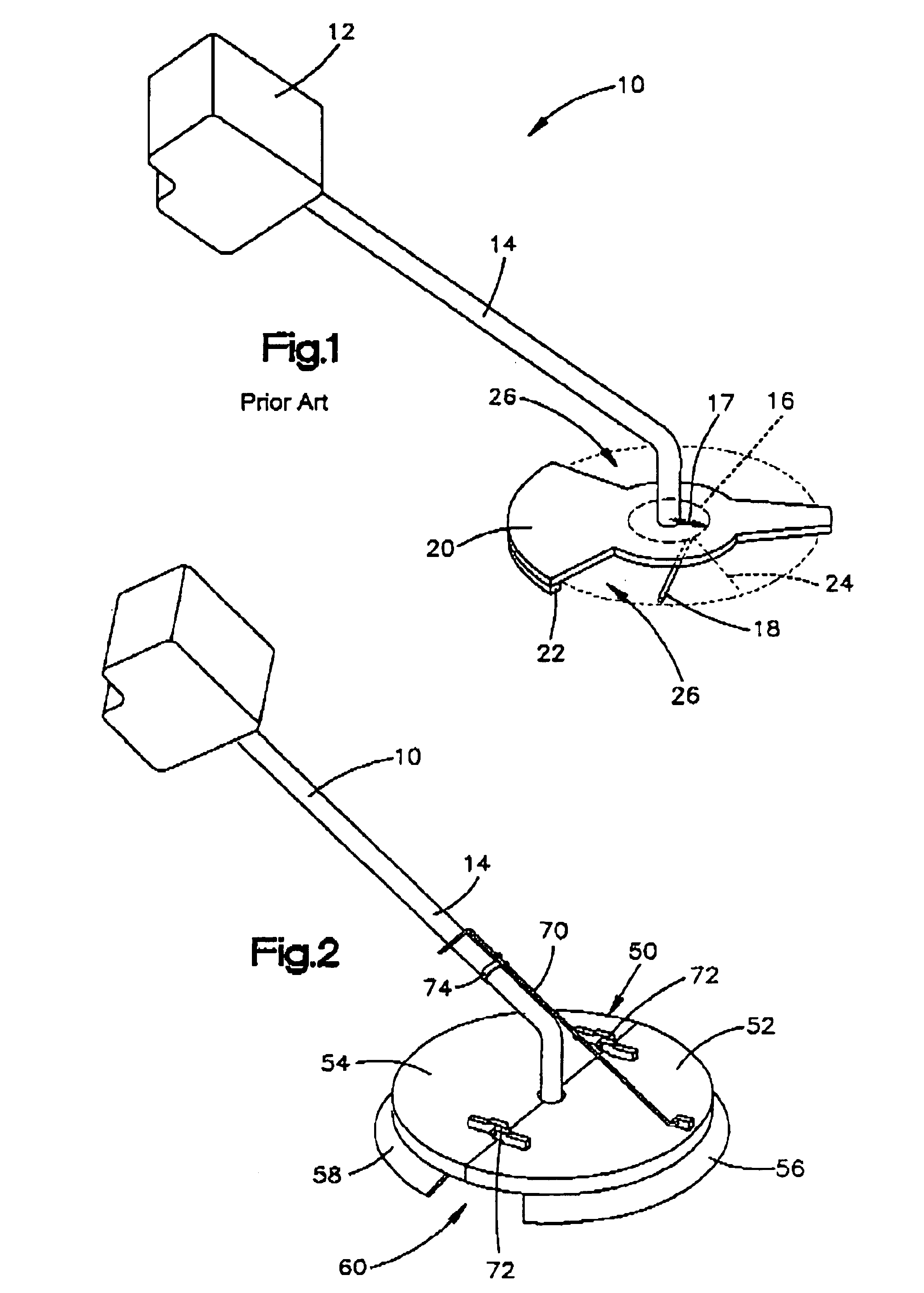
[0020]Referring now to FIG. 2, one embodiment of the present invention is illustrated. A circular adjustable covering assembly 50 is shown attached to the prior art weed trimmer 10 of FIG. 1. The assembly, according to the present invention, consists of a front semicircular element 52 and a rear semicircular element 54, both attached about the shaft 14 above the typical prior art weed trimmer guard 20. Although, in the present embodiment, the embodiment 50 is attached directly on top of a pre-existing rear facing guard 20, it should be readily understood that the present invention may be utilized in place of the typical prior art rear guard element 20.

[0021]The semicircular front and rear cover elements 52 and 54 each have a partially semicircular flange element 56 and 58 associated with it, respectively. These flange elements 56 and 58 help to compel weeds, vegetation, tall grasses, and other elements desired to be cut by the weed trimmer 10 cutting element 18 (not shown) toward th...

embodiment 60

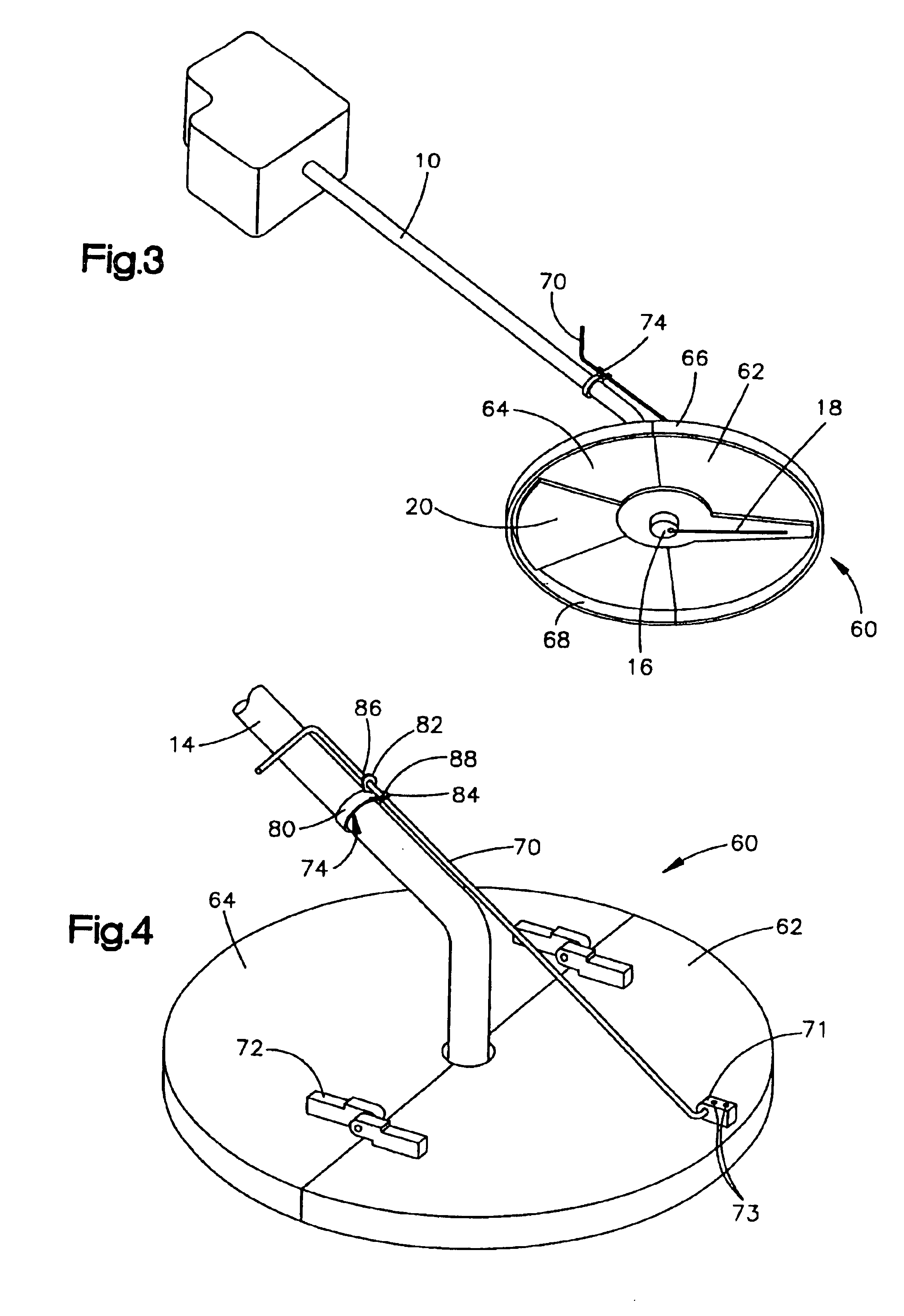
[0026]FIG. 4 is a more detailed view of the rod 70, locking element 74, and spring hinge element 72 as incorporated in the embodiment 60 shown in FIG. 3. The locking mechanism 74 is a tensioned metal butterfly spring device. The rod 70 is disposed between an upper finger projection 82 and a lower finger projection 84 through apertures 86 and 88, respectively. A base element 80 of the locking means 74 is clamped about the prior art weed trimmer shaft 14. By squeezing the upper butterfly element 82 and the lower butterfly element 84 toward each other, tension is released from the spring-like action of the elements 82 and 84, which would otherwise attempt to spread apart from each other and exert pressure on the rod element 70 through their interface with their respective apertures 86 and 88 with the rod element 70. By removing this tension, by squeezing 82 towards 84, the rod 70 can be easily slid upward or downward through the apertures 86 and 88 until the front cover 62 is compelled...

embodiment 90

[0029]Referring now to FIG. 5, another embodiment of the present invention 90 is depicted. Here, a front element 92 and a rear clement 94 are attached to a prior art weed trimmer shaft 14. In contrast to the embodiment of the invention depicted in FIG. 4, the invention embodiment 90 shown in FIG. 5 has two triangular shaped front and rear elements 92 and 94. Between the outer edge 93 of the rear element 94 and the outer edge 95 of the front element 92, a large aperture 96 is formed on both sides of the weed trimmer assembly. The gap 96 may be desired by a user who wishes some of the materials being mulched by the cutting element 18 to be expelled to the sides of the weed trimmer assembly. It may also be preferable to have a visual gap 96 so that a user of a conventional weed trimmer 10 can see the results of the trimming action by the cutting element 18 as he progresses through his cutting applications.

[0030]Referring again to FIG. 4, the front cover element 62 and rear cover elemen...


PUM


Abstract

The present invention provides for an article and method for an improved weed trimmer cover that prevents unwanted projectile and debris distributions. A preferred embodiment of the weed trimmer comprises a domed guard structure that encompasses the effective cutting range of a prior art weed trimmer. Alternative embodiments may comprise elements that protect only portions of front, side and rear cutting areas. Embodiments of the invention also allow a user to lift up a cover element to allow close work among obstructions. Embodiments of the present invention also improve the performance of prior art weed trimmers by increasing cutting performance and preventing flexible materials from wrapping about the cutting elements and shafts.

Description

CROSS REFERENCE TO RELATED APPLICATION[0001]This application claims the benefits of provisional patent application Ser. No. 60 / 399,595, confirmation number 2681, filed Jul. 30, 2002.FIELD OF THE INVENTION[0002]The present invention provides a method and apparatus for providing protection and control of debris and projectiles emitted by power tools. More particularly, the present method and apparatus provide an improved protective cover and performance enhancing system for powered lawn care tools, such as powered weed trimmers.BACKGROUND OF THE INVENTION[0003]Weed trimmers are popular lawn care items in use by both consumers and lawn care professionals. The most popular form of power weed trimmer is the gasoline or electric engine device wherein a motor drives a nylon cord in a rapid rotary fashion. The cord then strikes and cuts down thin stemmed vegetations, most typically grasses and other shrubs and weeds. Weed trimmers are made by many different manufacturers. Typical well-known...

Claims


Application Information

Patent Timeline
Patent Type & Authority Patents(United States)
IPC IPC(8): A01D75/00A01D75/20
CPCA01D34/4167A01D75/206A01D2101/00
Inventor PETERSON, FRED J.
Owner PETERSON MARGARET
Why Eureka
Try Eureka