Wall structure with corner connectors

a wall structure and corner connector technology, applied in the direction of girders, shock-proofing, joists, etc., can solve the problems of eccentric load transfer, exterior sheathing and exterior bracing not efficiently transferring shear loads

Inactive Publication Date: 2005-05-17
THE STEEL NETWORK
View PDF12 Cites 54 Cited by
  • Summary
  • Abstract
  • Description
  • Claims
  • Application Information

AI Technical Summary

Benefits of technology

[0009]In another embodiment of the present invention, the wall structure is provided with at least one diagonal brace that extends through openings formed in a series of studs that form a part of the wall structure. The diagonal brace, which can be rigid or flexible, includes opposite end portions that project into opposed corner areas of the wall structure. Disposed in each corner area is a bracket that is secured to one of the opposed members of the wall structure. Further, the bracket includes an opening therein through which an end portion of the brace extends. Secured to the end of the brace adjacent the bracket is a retainer that effectively retains the end portion of the brace within the bracket and prevents the end portion of the brace from pulling inwardly from the opening in the bracket.

Problems solved by technology

However, because of the location of the sheathing or the bracing, the loads transferred are transferred eccentrically.
This, of course, results in the loads tending to twist the wall structure and its components, and consequently these loads are not directly and concentrically transferred to the foundation or other termination points.
In the end, such exterior sheathing and exterior bracing does not efficiently transfer shear loads.

Method used


Image

  • Wall structure with corner connectors
  • Wall structure with corner connectors
  • Wall structure with corner connectors

Examples


Embodiment Construction

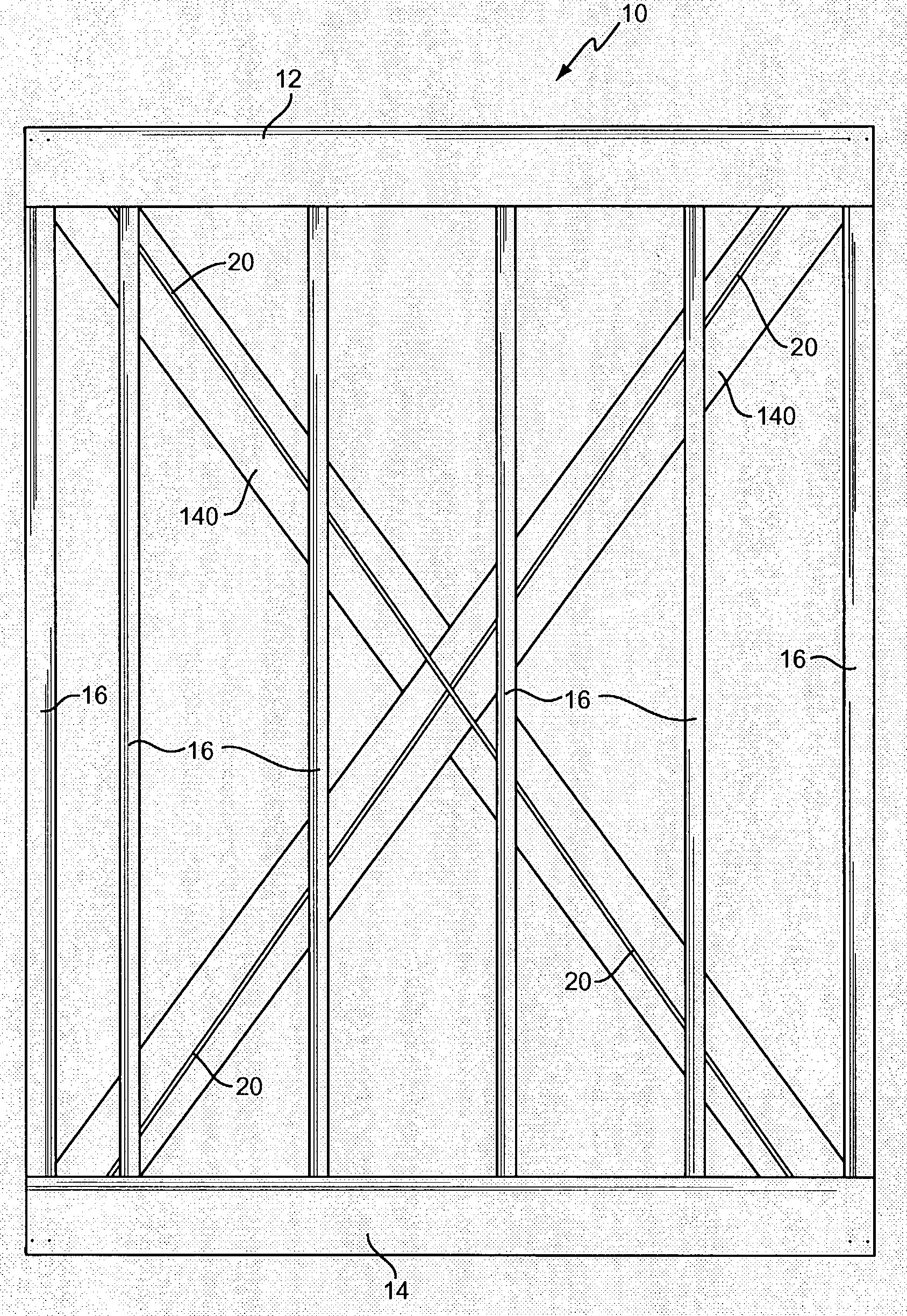
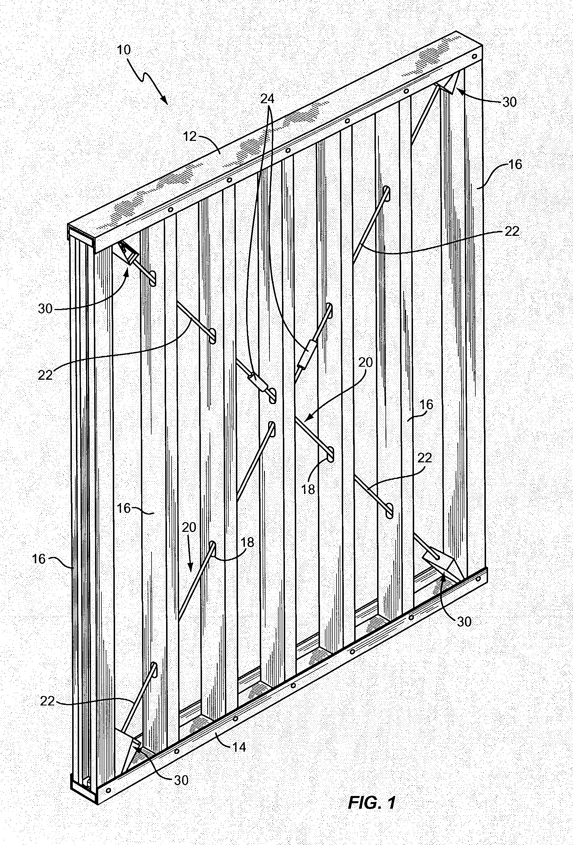
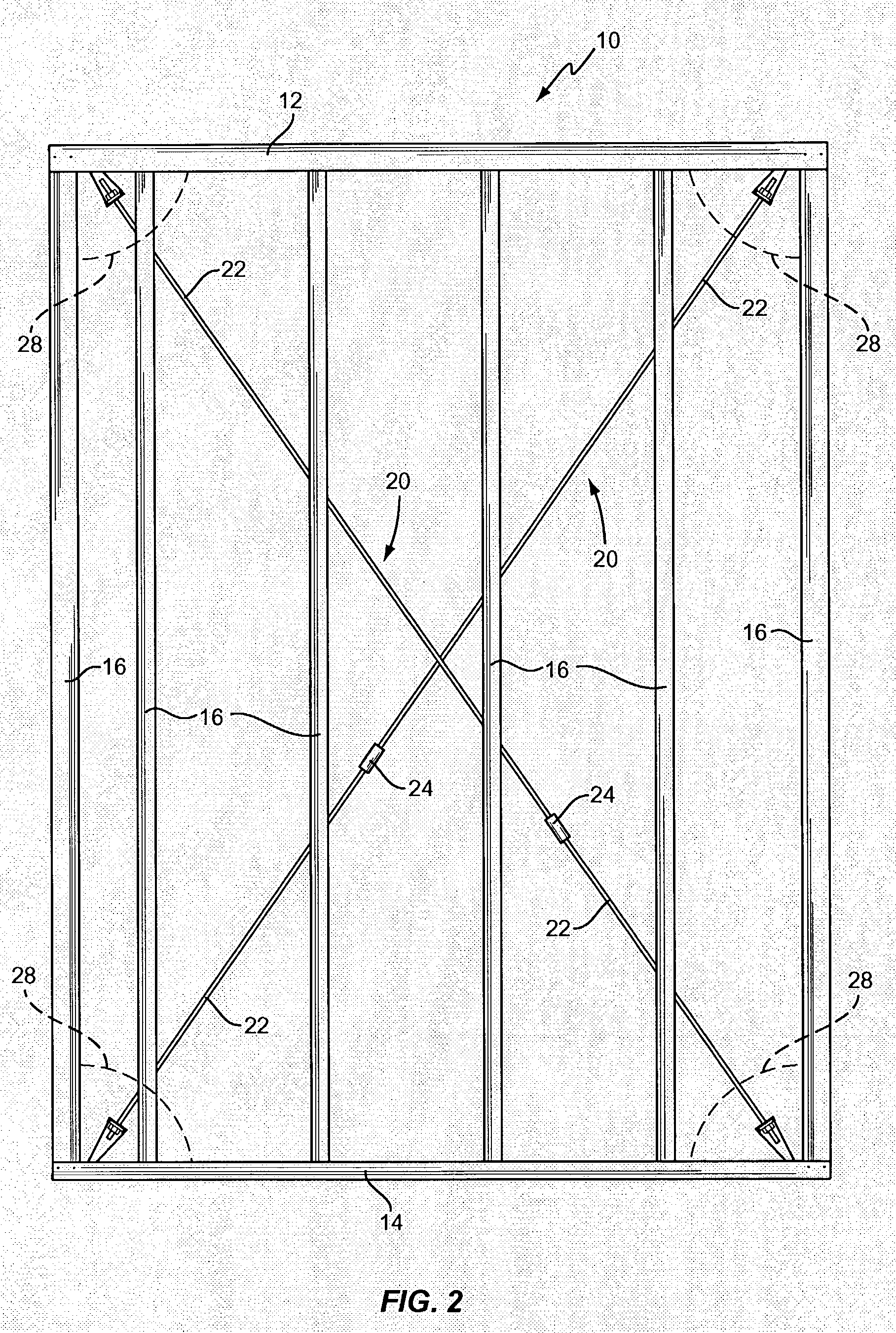
[0030]With further reference to the drawings, the wall structure or wall module of the present invention is shown therein and indicated generally by the numeral 10. Wall structure 10 basically comprises an upper member 12 and a lower member 14. Members 12 and 14 may assume various configurations but in one embodiment, upper member 12 and lower member 14 would be of a generally U-shaped channel construction. In the case of the U-shaped channel construction, each member 12 and 14 would include a central or web portion and a pair of upturned, or downturned, as the case may be, flanges.

[0031]Secured between the upper member 12 and lower member 14 is a plurality of spaced apart studs 16. The studs are secured to both the upper and lower members 12 and 14. Studs 16 may be secured to the upper and lower members 12 and 14 in any number of ways. For example, fasteners such as screws can be extended through the flanges of the upper and lower members 12 and 14 into the respective studs. In add...


PUM


Abstract

A wall structure adapted to be fabricated in sections or modules and comprises an upper member, a lower member, a plurality of studs interconnected between the upper and lower members with respective studs including openings therein, and at least one diagonal brace member or strap extending diagonally across the wall structure. In one embodiment the strap is extended to opposed corner areas where opposed end portions of the strap are fastened to a portion of the upper or lower member and to a portion of an adjacent column or stud.

Description

CROSS-REFERENCE TO RELATED APPLICATION[0001]This is a continuation-in-part of U.S. patent application Ser. No. 10 / 058,958 filed Jan. 28, 2002.FIELD OF THE INVENTION[0002]The present invention relates to wall structures and more particularly to wall structures that may be fabricated in sections or modules.BACKGROUND OF THE INVENTION[0003]It is important in the design of wall structures to provide both lateral strength and lateral rigidity. Lateral strength is required to resist horizontal loads due to, for example, wind and earthquake forces. If the wall structure is properly designed and constructed, components of the wall will transfer these horizontal or shear forces to adjacent elements in the load path such as other wall components, floors or foundations.[0004]Lateral rigidity is required to prevent the floors and roof from excessive side-sway. If the walls are sufficiently rigid, they will prevent floor and roof framing members from moving off their supports. In addition, build...

Claims


Application Information

Patent Timeline
Patent Type & Authority Patents(United States)
IPC IPC(8): E04B1/08E04B1/02E04C2/38E04B1/24
CPCE04B1/08E04C2/384E04B2001/2496
Inventor DIGIROLAMO, EDWARD R.TORRES, MICHAEL L.HERRMANN, ROBERT W.HERRMANN, AARON M.BOYD, THOMAS C.BENNETT, GARY
Owner THE STEEL NETWORK
Why Eureka
Try Eureka