Fall impact apparatus

a technology of falling impact and apparatus, which is applied in the direction of instruments, material analysis, and using mechanical means, etc., can solve the problems of site collision with the surface that cannot be kept constant, test results that cannot be repeated, and change the attitudinal angle of the test subj

Inactive Publication Date: 2005-05-17
UNIDEN
View PDF8 Cites 19 Cited by
  • Summary
  • Abstract
  • Description
  • Claims
  • Application Information

AI Technical Summary

Benefits of technology

[0011]In order to achieve the object described above, a fall impact apparatus according to the present invention comprises a test subject fixing member for fixing a test subject which is to be tested for impact strength at a desired attitudinal angle, a hoisting and dropping member for raising and along the falling direction of the test subject, dropping the test subject fixing member to which the test subject is fixed, and a dropping subject surface structured so as to collide only with the test subject at the terminal end of the falling direction without interference of the hoisting and dropping member when the hoisting and dropping member is dropped together with the test subject fixing member. The test subject fixing member is supported by the hoisting and dropping member without being affixed thereto such that when the test subject collides with the dropping subject surface, the fixing member separates freely from the hoisting and dropping member.
[0012]According to this construction, the test subject can be fixed at any desired attitudinal angle prior to the start of the drop test, and this attitudinal angle can be maintained until the moment of impact with the dropping subject surface. Since control can be performed such that a desired site of the test subject collides with the dropping subject surface at a desired angle, drop test results can be reproduced repeatedly.
[0013]Furthermore, the test subject fixing member is supported by the hoisting and dropping member without being affixed thereto, and therefore separates from the hoisting and dropping member without resistance as the test subject collides with the dropping subject surface. As a result, effects thereof on the drop test values can be prevented.
[0014]Here, “supported without being affixed” means that the test subject fixing member and the hoisting and dropping member are not fixed to each other in a manner which would affect the drop test values. For example, the two members are not fixed together using adhesion means such as an adhesive or adhesive tape, and thus upon impact the test subject fixing member separates from the hoisting and dropping member easily, without resistance, and without receiving force therefrom. In other words, “supported without being affixed” corresponds to a state in which drop test results that can be considered substantially identical to a case in which the test subject falls independently and freely can be obtained.
[0019]According to the fall impact apparatus of the present invention as described above, the attitudinal angle of the test subject can be fixed and maintained by the test subject fixing member until the moment of impact with the dropping subject surface, and thus drop test results can be reproduced repeatedly. Moreover, the test subject fixing member separates from the hoisting and dropping member as the test subject collides with the dropping subject surface, and thus drop test results that can be considered substantially identical to a case in which a test subject is dropped independently and freely can be obtained.

Problems solved by technology

When caused to free fall from a sufficiently high position, however, the test subject rotates during the free fall, and thus the site which collides with the surface cannot be kept constant.
As a result, test results cannot be reproduced repeatedly.
However, in the aforementioned fall impact apparatus which comprises the hand-like shaped apparatus, the test subject falls freely for a short period of time following release from the apparatus, and thus change may occur in the attitudinal angle of the test subject.
Moreover, a position detection means and a means for automatically releasing the test subject have to be provided, which tends to complicate the structure of the device.
In the dropping device which holds the test subject by a cord-form material, the cord-form material itself may swing or vibrate during the dropping process due to air resistance or the like, and hence the attitude of the test subject cannot be sufficiently maintained as the attitude originally set prior to starting the free fall action.

Method used


Image

  • Fall impact apparatus
  • Fall impact apparatus
  • Fall impact apparatus

Examples


Embodiment Construction

[0026]Preferred embodiments of the present invention will be described below with reference to the drawings. Note that the embodiments described below are examples to illustrate the present invention, and the present invention is not limited to or by these embodiments.

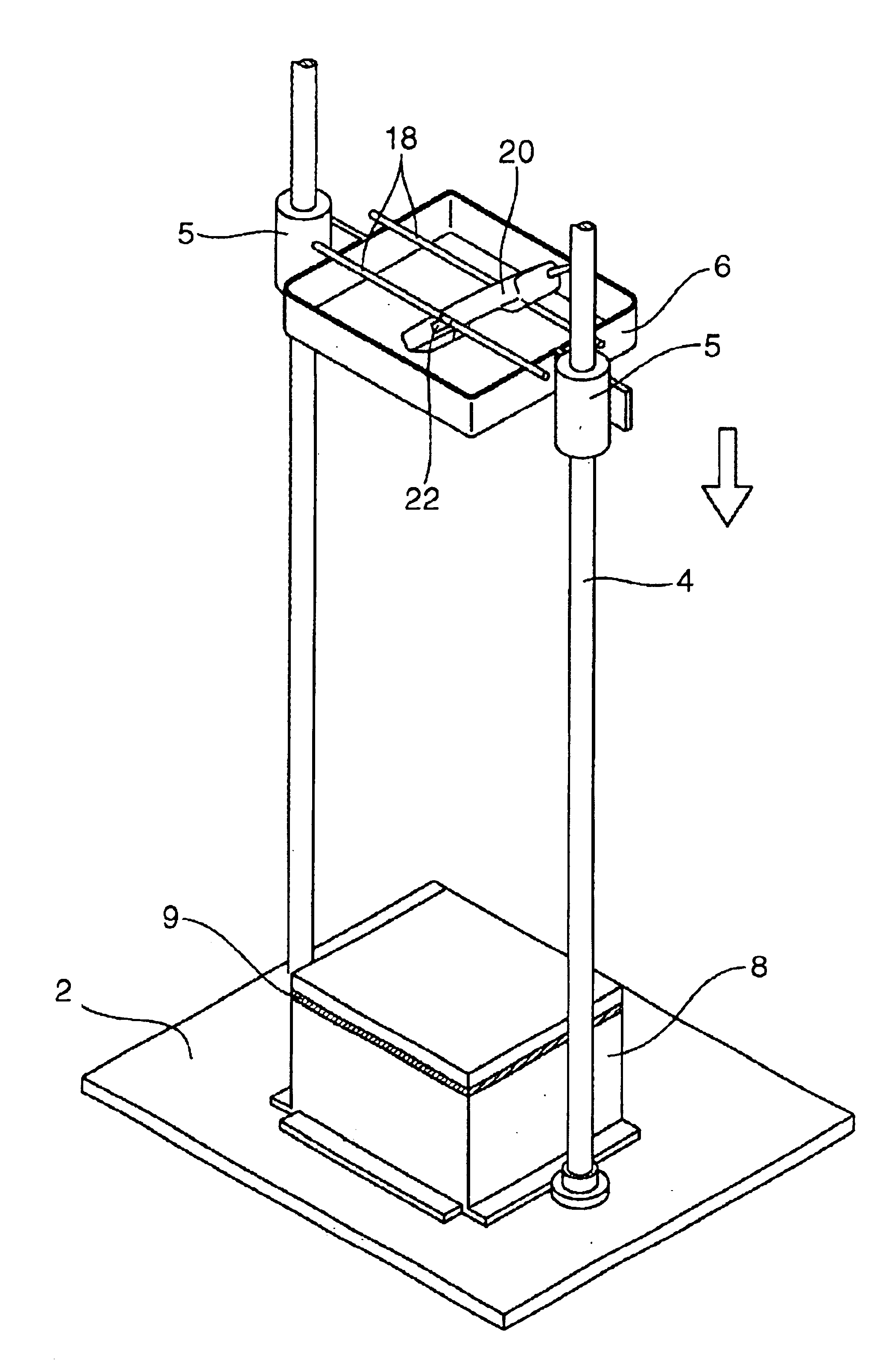
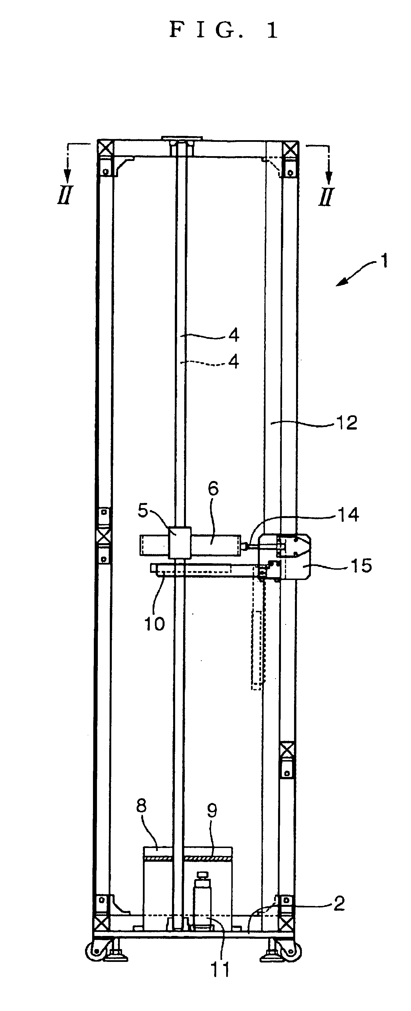
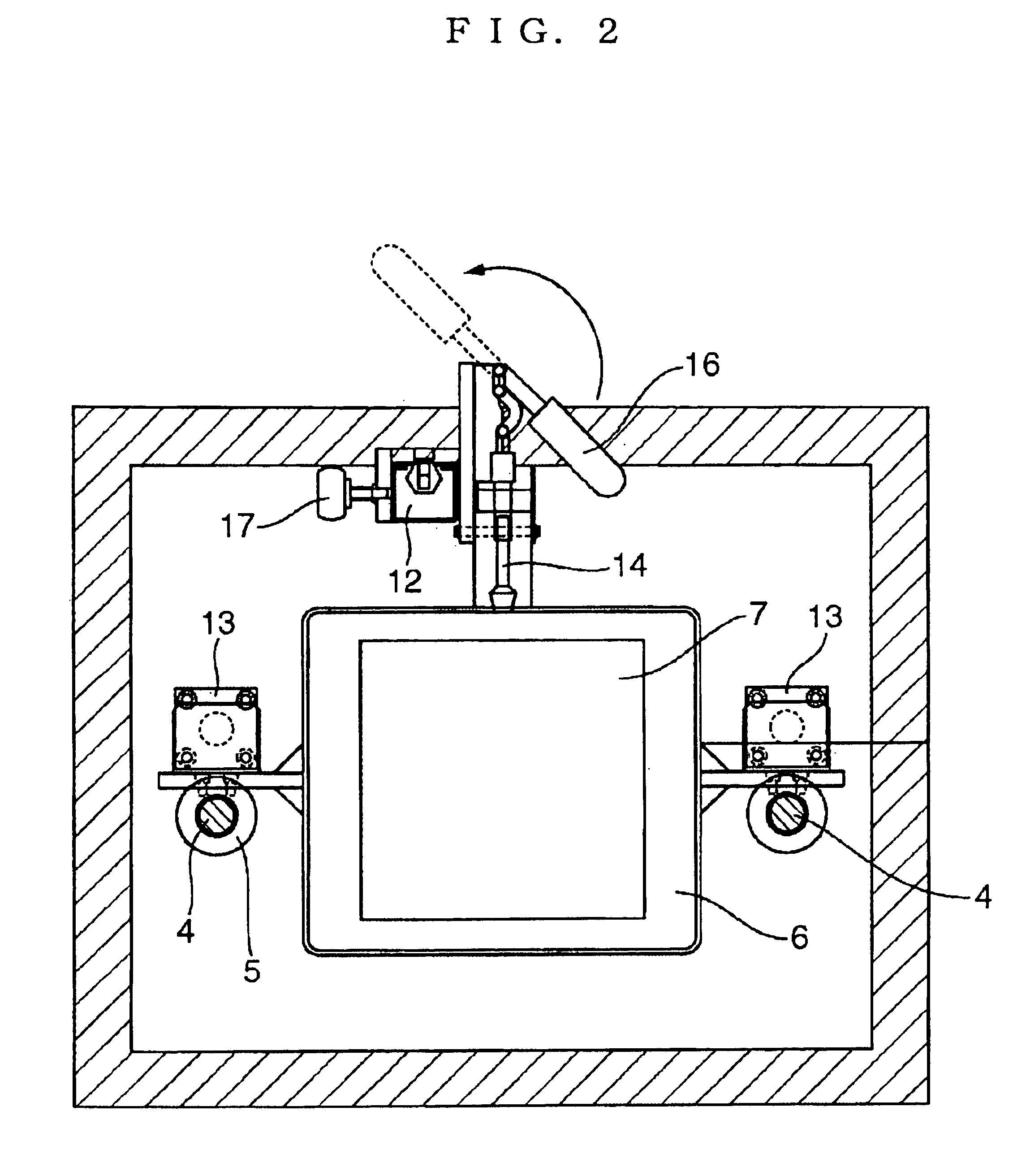
[0027]FIG. 1 is a side view of a fall impact apparatus prior to the setting of a test subject and a test subject fixing member, FIG. 2 is a plan view showing a hoisting and dropping member and a stopper mechanism, FIG. 3 is a side view of the test device following the setting of the test subject and test subject fixing member, FIG. 4 is a front view of the test device for illustrating the situation in which a drop test is implemented, FIG. 5 is a partial perspective view of the test device showing the test subject as it drops, and FIG. 6 is a partial perspective view of the test device showing the test subject having collided with the surface.

[0028]First, referring to FIGS. 5 and 6, the schematic construction of the fa...


PUM

PropertyMeasurementUnit
fall impact resistanceaaaaaaaaaa
attitudinal angleaaaaaaaaaa
impact resistanceaaaaaaaaaa

Abstract

An object of the present invention is to provide a fall impact apparatus, namely a fall impact apparatus, which is capable of fixing the attitudinal angle of a test subject during a drop test until the moment at which the test subject collides with a dropping subject surface.The fall impact apparatus includes a test subject fixing member for fixing a test subject which is to be tested for impact strength at a desired attitudinal angle, a hoisting and dropping member for raising and dropping the test subject fixing member to which the test subject is fixed along the falling direction of the test subject, and a dropping subject surface structured so as to collide only with the test subject at the terminal end of the falling direction without interfering with the hoisting and dropping member when the hoisting and dropping member is dropped together with the test subject fixing member. The test subject fixing member is supported by the hoisting and dropping member without being affixed thereto such that when the test subject collides with the dropping subject surface, the fixing member separates freely from the hoisting and dropping member.

Description

BACKGROUND OF THE INVENTION[0001]1. Field of the Invention[0002]The present invention relates to a drop testing device, namely a fall impact apparatus, for testing the tolerance of a product against free fall impact.[0003]2. Description of the Related Art[0004]Portable electronic devices such as portable telephones, MD players, and electronic dictionaries have conventionally been tested for impact resistance using a fall impact apparatus in order to improve the reliability of such products.[0005]In such fall impact apparatus, the test subject must be dropped in a free fall manner or as close to such free fall conditions as possible. When caused to free fall from a sufficiently high position, however, the test subject rotates during the free fall, and thus the site which collides with the surface cannot be kept constant. As a result, test results cannot be reproduced repeatedly.[0006]In order to solve this problem, a fall impact apparatus using a hand-like shaped apparatus which is c...

Claims


Application Information

Patent Timeline
Patent Type & Authority Patents(United States)
IPC IPC(8): G01N3/303G01N3/30
CPCG01N3/303
Inventor ISHIKAWA, KATSUMI
Owner UNIDEN
Why Eureka
Try Eureka