Charge control device and battery pack employing it

a control device and battery pack technology, applied in the direction of secondary cell servicing/maintenance, cell components, safety/protection circuits, etc., can solve the problems of difficult to correct for a variation in level, inability to make the most of the charge capacity of the secondary cell, and inability to accurately control the charging of the secondary cell. , to achieve the effect of accurately controlling the charging of the secondary cell

Inactive Publication Date: 2005-05-17
ROHM CO LTD
View PDF2 Cites 7 Cited by
  • Summary
  • Abstract
  • Description
  • Claims
  • Application Information

AI Technical Summary

Benefits of technology

[0009]An object of the present invention is to provide a charge control device that can accurately control the charging of a secondary cell by canceling the influence of stress occurring when an IC is packaged or mounted on a circuit board and other factors, and to provide a battery pack employing such a charge control device.
[0010]To achieve the above object, according to the present invention, a charge control device is provided with a full charge detection circuit for checking whether a secondary cell is in a fully charged state or not based on the charge voltage and / or the charge current of the secondary cell, a control circuit for controlling the feeding of electric power to the secondary cell according to the output of the full charge detection circuit, a storage circuit for storing control information, and a setting circuit for setting the level of the charge voltage and / or the charge current at which the full charge detection circuit recognizes the fully charged state according to the control information read from the storage circuit. Here, the control information is fed into the storage circuit from outside. With this configuration, it is possible to accurately control the charging of a secondary cell by canceling the influence of stress occurring when an IC is packaged or mounted on a circuit board and other factors.

Problems solved by technology

This makes it impossible to make the most of the charge capacity of the secondary cell 2′.
This makes it extremely difficult to correct for a variation in the level at which to recognize the fully charged state.
This makes it impossible to make the most of the charge capacity of the secondary cell 2′.
Moreover, the sense resistor 6′, connected externally, hampers the scaling-down and cost reduction of the battery pack 1′.

Method used


Image

  • Charge control device and battery pack employing it
  • Charge control device and battery pack employing it
  • Charge control device and battery pack employing it

Examples


Embodiment Construction

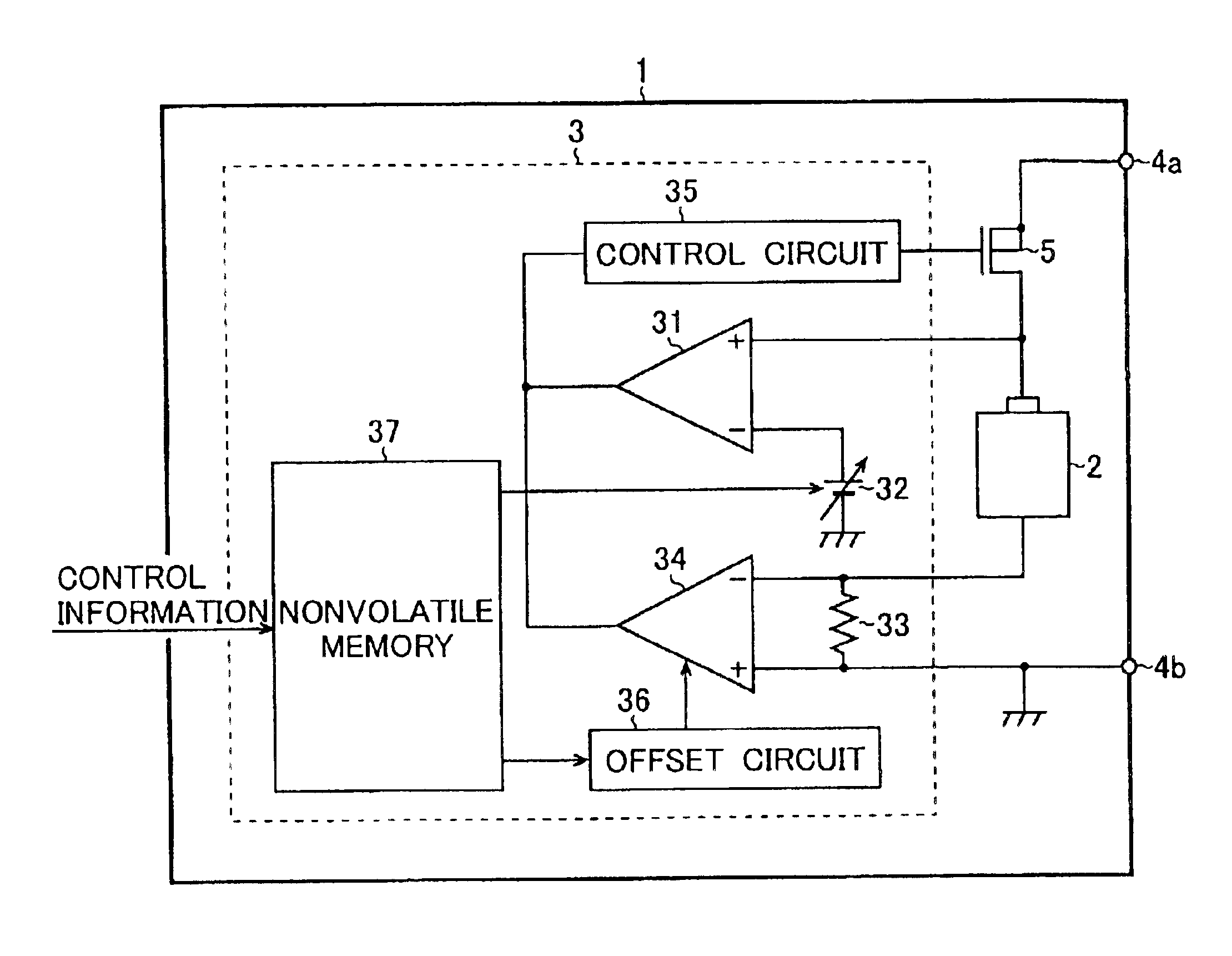
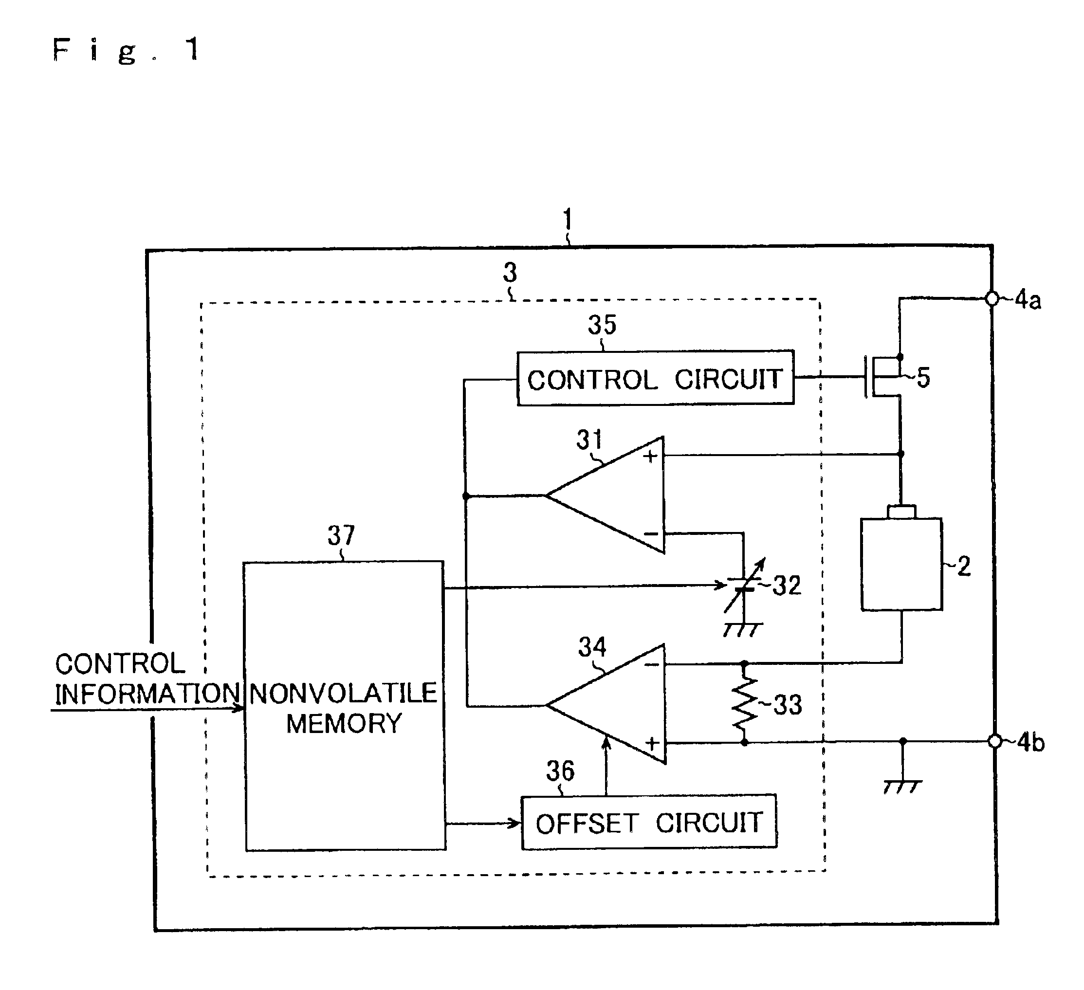
[0014]FIG. 1 is a diagram showing an outline of the configuration of an example of a battery pack incorporating a charge control device embodying the invention. The battery pack 1 of this embodiment is composed of a rechargeable secondary cell 2 (for example, a lithium ion cell), a charge control IC 3 for controlling the charging of the secondary cell 2 by monitoring its charge state, feed terminals 4a and 4b to which direct-current electric power is fed from a charger (not shown), and a switch device 5 (for example, a MOS transistor) connected between the feed terminal 4a and the positive electrode of the secondary cell 2.

[0015]The charge control IC 3 is built by sealing into a single package a first full charge detection circuit 31 for checking whether the secondary cell 2 is in the fully charged state or not by comparing its charge voltage with a predetermined reference voltage, a variable direct-current voltage source 32 for generating the reference voltage, a sense resistor 33 ...


PUM

PropertyMeasurementUnit
charge voltageaaaaaaaaaa
charge currentaaaaaaaaaa
electric poweraaaaaaaaaa

Abstract

A charge control device has a full charge detection circuit for checking whether a secondary cell is in a fully charged state or not based on the charge voltage and / or the charge current of the secondary cell, a control circuit for controlling the feeding of electric power to the secondary cell according to the output of the full charge detection circuit, a storage circuit for storing control information, and a setting circuit for setting the level of the charge voltage and / or the charge current at which the full charge detection circuit recognizes the fully charged state according to the control information read from the storage circuit. The control information is fed into the storage circuit from outside. With this configuration, it is possible to accurately control the charging of a secondary cell by canceling the influence of stress occurring when an IC is packaged or mounted on a circuit board and other factors.

Description

BACKGROUND OF THE INVENTION[0001]1. Field of the Invention[0002]The present invention relates to a charge control device for controlling the charging of a secondary cell or battery (hereinafter collectively referred to as a “secondary cell” throughout the specification and the claims) by monitoring its charge state, and relates also to a battery pack employing such a charge control device.[0003]2. Description of the Prior Art[0004]FIG. 2 is a diagram showing an outline of the configuration of an example of a conventional battery pack incorporating a charge control device. The battery pack 1′ shown in this figure is composed of a rechargeable secondary cell 2′, a charge control IC 3′ for controlling the charging of the secondary cell 2′ by monitoring its charge state, feed terminals 4a′ and 4b′ to which direct-current electric power is fed from a charger (not shown), a switch device 5′ connected between the feed terminal 4a′ and the positive electrode of the secondary cell 2′, and a ...

Claims


Application Information

Patent Timeline
Patent Type & Authority Patents(United States)
IPC IPC(8): H02J7/00H02J7/10H01M2/10H01M10/42H01M10/44
CPCH01M10/4257H02J7/0031H02J2007/0037H02J7/00302Y02E60/10
Inventor FUJII, MASAAKI
Owner ROHM CO LTD
Why Eureka
Try Eureka