Modular Energy System for Storing and Releasing Energy

a module-based energy system and energy storage technology, applied in secondary cells, battery service/maintenance, safety/protection circuits, etc., can solve the problems of only being able to put the system in operation, the configuration of the stack cannot be changed without the risk of interrupting the power supply, and the cable end, etc., to achieve sufficient robustness, increase modularity, and increase efficiency

Inactive Publication Date: 2020-08-27
WATTSUN POP UP POWER BV
View PDF0 Cites 4 Cited by
  • Summary
  • Abstract
  • Description
  • Claims
  • Application Information

AI Technical Summary

Benefits of technology

[0065]In this way the power of the batteries of the stack is exchanged with an increased efficiency while still ensuring sufficient robustness and increased modularity. Only the battery of the outlet power pack is able to be charged from the power of other batteries in the stack in order to ensure continued operation even when all other non-outlet power packs of the stack are for example being exchanged for replenished non-outlet power packs.
[0066]All other battery power is directed with an increased efficiency to the power outlet module. This also limits charging and decharging cycles the batteries of the power packs are subjected to, thereby further increasing robustness and longevity of the power packs.

Problems solved by technology

This however demands extensive technical measures to ensure correct operation by a user lacking a sufficient level of technical knowledge as, in case of improper coupling of the cables damage to the device can occur.
However, even then damage can occur, for example when a user inadvertently tries to force a cable end in a connector of which the size does not match, thereby resulting in damage to the cable end, connector and / or the electrical systems of the device.
It is however clear that such system can only be put in operation once the desired number of power packs for the stack is chosen and the required connections are established between the power packs and an output module or invertor module of the stack.
During operation, this means, when electric power is provided by an output module or invertor module to an electric load, the configuration of the stack cannot be changed without the risk of interrupting the power supplied to the electric load.
For example, when during operation a battery of a power bank runs depleted it is not possible to easily extract such a power bank from the stack, as at least the output module or inverter module and / or other power banks will be stacked on top of it.
Additionally, removal of a power bank during operation would require disconnecting the cables or connectors of this power bank, thereby interrupting the coupling of the output module or invertor module with some or in a worst scenario even all of the other power banks of the stack, thereby leading to the risk of insufficient power being supplied or even interruption of the power supplied to the electric load.
Still further, as during operation large currents are often flowing through the connectors or cables of the power packs in the stack, a sudden disconnection of the connectors or cables often results in unacceptable power surges leading to the risk of damaging electronic circuits and leading to safety and fire hazards because of electric arc formation during disconnection.
Similar problems occur when during operation a power bank would be added to the stack as when establishing a coupling of the new power bank with the other power banks of the stack, this would also lead to the risks associated with sudden power surges, electric arc formation, etc.

Method used


Image

  • Modular Energy System for Storing and Releasing Energy
  • Modular Energy System for Storing and Releasing Energy
  • Modular Energy System for Storing and Releasing Energy

Examples


Embodiment Construction

)

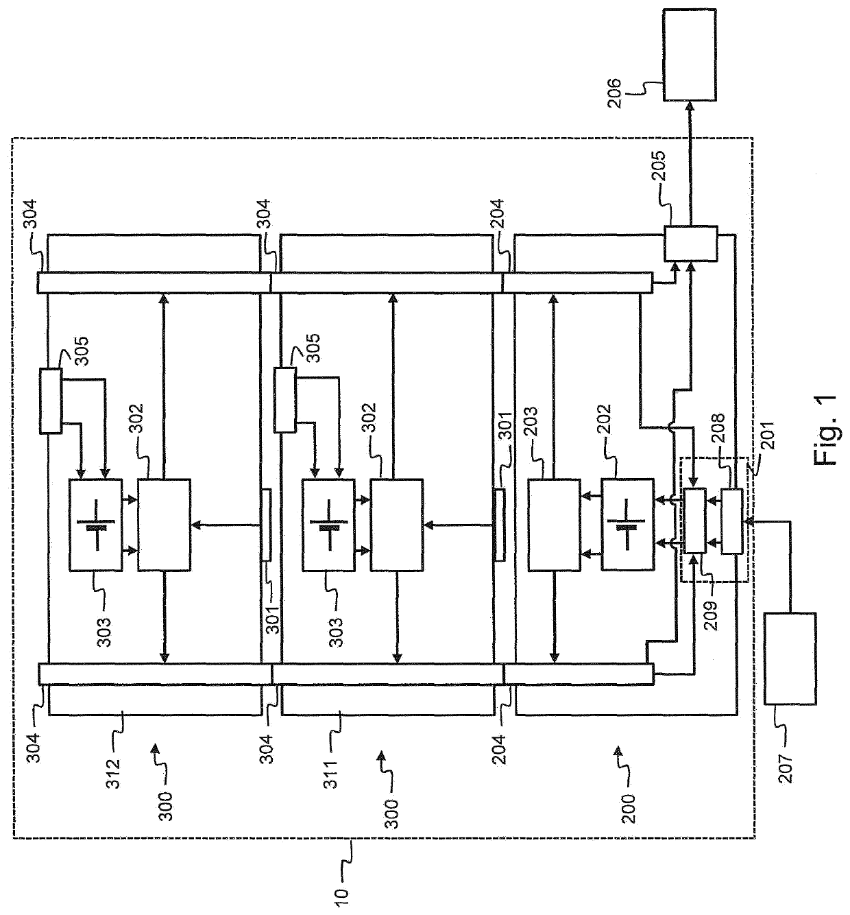
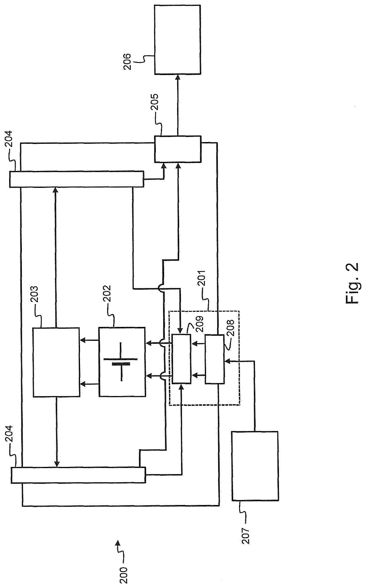
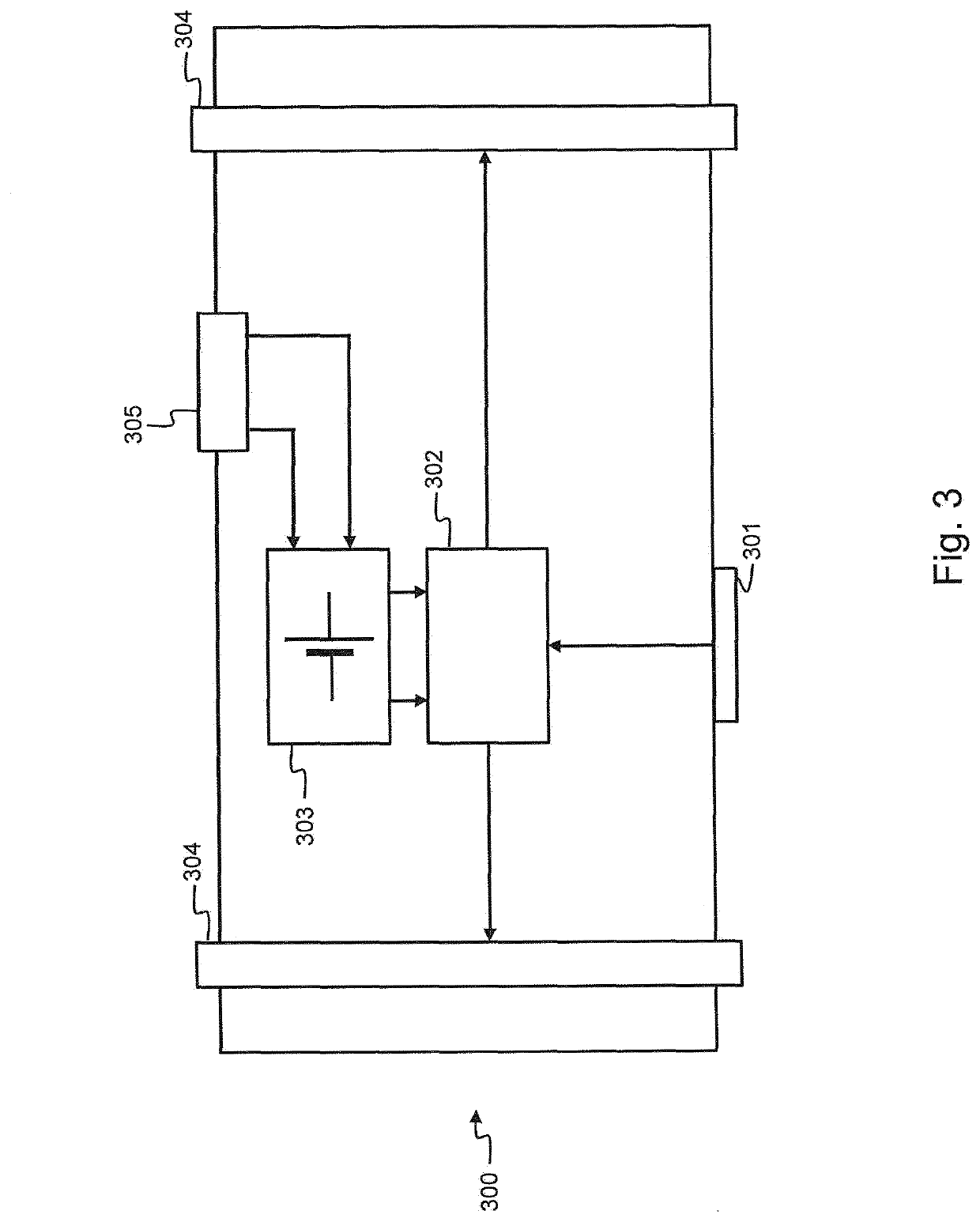
[0099]According to an embodiment, the invention relates to a modular system for storing and outputting electrical energy, the system comprising a stack, the stack comprising a plurality of power packs. FIG. 1 illustrates such a stack, comprising only one outlet power pack 200 and two non-outlet power packs 300, a first non-outlet power pack 311 on top of the outlet power pack 200 and a second non-outlet power pack 312 on top of the first power pack 311.

[0100]Each power pack also comprises a power coupling module. As for the outlet power pack 200 this power coupling module is presented by 204, while as for the non-outlet power packs 300 the power coupling module is presented by 304.

[0101]If a power pack is stacked on top of another pack, for example power pack 311 is stacked on 200, the power coupling modules 204 and 304 of the two packs are configured such that electrical power may be exchanged. On top of the first non-outlet power pack 311 another non-outlet power pack 312 can be ...


PUM

PropertyMeasurementUnit
voltageaaaaaaaaaa
voltageaaaaaaaaaa
electrical energyaaaaaaaaaa

Abstract

A modular system for storing and outputting electrical energy, the system comprising a stack, the stack (10) comprising a plurality of power packs (200, 300) removably stacked one on top of the other.

Description

FIELD OF THE INVENTION[0001]The present invention relates to a modular energy system for storing and releasing energy to a wide range of electrical loads. More in particular, the present invention relates to an energy system comprising a plurality of power packs that are portable, removably stackable, mutually electrically connectable, rechargeable, etc. in a modular way.BACKGROUND OF THE INVENTION[0002]Due to the implementation of power generating stations, like photovoltaic systems and wind turbines, nowadays the generation of electrical energy is more and more decentralized. Hence, in order to minimize energy losses originating from transmission and distribution of electrical energy, such power stations are preferably located close to the load they serve.[0003]Yet such decentralized power stations are mostly dependent regarding to the instantaneous level of power generation on parameters out of their control. Such parameters can be for example sun radiation characteristics or win...

Claims


Application Information

Patent Timeline
Patent Type & Authority Applications(United States)
IPC IPC(8): H02J7/00H01M10/48H01M10/42H01M10/44H01M2/10H01M2/20H01M10/46H02J7/34H01M50/204H01M50/271H01M50/502
CPCH01M10/4257H01M2010/4271H02J7/0045H01M10/4207H01M10/441H02J7/0031H01M10/46H01M2220/10H01M10/482H01M2/1077H02J7/342H02J7/0047H02J7/0013H01M2/206H01M10/446H01M10/448H02J7/0036H01M2200/00H01M50/502H01M50/204H01M50/271
Inventor SCHURINK, PAULUS JOHANNES JACOBUS MARIABERGMAN, LUCAS ANTONIUS MARTIJNOLIESLAGERS, KOEN JOZEF
Owner WATTSUN POP UP POWER BV
Why Eureka
Try Eureka