Liquid ejecting head and liquid ejecting apparatus

a liquid ejector and liquid ejector technology, applied in printing and other directions, can solve the problems of clogging the nozzle, affecting the effect of liquid ejector, and difficult to effectively prevent the attachment of ink to the nozzle face, etc., to achieve effective suppression of liquid attachment, and suppress the effect of liquid attachmen

Active Publication Date: 2017-03-02
SEIKO EPSON CORP
View PDF7 Cites 4 Cited by
  • Summary
  • Abstract
  • Description
  • Claims
  • Application Information

AI Technical Summary

Benefits of technology

[0006]An advantage of some aspects of the invention is to effectively suppress attaching of liquid to a nozzle face using a simple configuration.
[0007]According to an aspect of the invention, there is provided a liquid ejecting head which includes a nozzle face on which nozzles ejecting liquid onto a medium are formed; a first region with a liquid repelling property which is connected to a peripheral edge of a nozzle when planarly viewed; and a second region with a liquid repelling property lower than that in the first region, which is connected to a peripheral edge of a nozzle when planarly viewed. In the above configuration, a region which is connected to a peripheral edge of the nozzle, when planarly viewed (that is, region at periphery of nozzle), includes a first region with a liquid repelling property, and a second region with a liquid repelling property which is lower than that in the first region. Since there is a tendency that it is difficult to charge the second region with the low liquid repelling property, compared to the first region, the second region is operated so as to suppress charging of liquid which is ejected from the nozzle. Accordingly, it is also possible to suppress attaching of liquid to the nozzle face due to charging which is caused by the liquid-repellent film, not only to suppress attaching of liquid to the nozzle face using a liquid repelling property in the first region. That is, according to the above configuration, it is possible to effectively suppress attaching of liquid to the nozzle face using a simple configuration.
[0008]The liquid ejecting head may include a liquid-repellent film which configures the nozzle face, in which the first region may be a region in which a liquid-repellent film is formed, and the second region may be a region in which the liquid-repellent film is not formed. In the above configuration, a region in which the liquid-repellent film is formed is set to the first region, and a region in which the liquid-repellent film is not formed is set to the second region. Accordingly, there is an advantage that it is possible to easily form the first region and the second region depending on whether to provide the liquid-repellent film or not.

Problems solved by technology

In a liquid ejecting head which ejects liquid such as ink from a plurality of nozzles which are formed on a nozzle face, there is a problem in that part of liquid (for example, fine liquid droplets which are misty) ejected from the plurality of nozzles is attached to the nozzle face.
In addition, when ink is attached to the nozzle face, it causes an ejecting failure such as clogging of a nozzle, or staining of a medium.
In a technology in JP-A-2007-331127, since a liquid-repellent layer is formed so as to be connected to a peripheral edge of a nozzle in the entire periphery of the nozzle when planarly viewed, in practice, it is difficult to effectively prevent attaching of ink to the nozzle face by sufficiently suppressing charging of ink which is caused by the liquid-repellent layer.
When there is an error in landing position of liquid in the transport direction of the medium, a belt-shaped printing irregularity in a direction orthogonal to the transport direction can occur.

Method used


Image

  • Liquid ejecting head and liquid ejecting apparatus
  • Liquid ejecting head and liquid ejecting apparatus
  • Liquid ejecting head and liquid ejecting apparatus

Examples


first embodiment

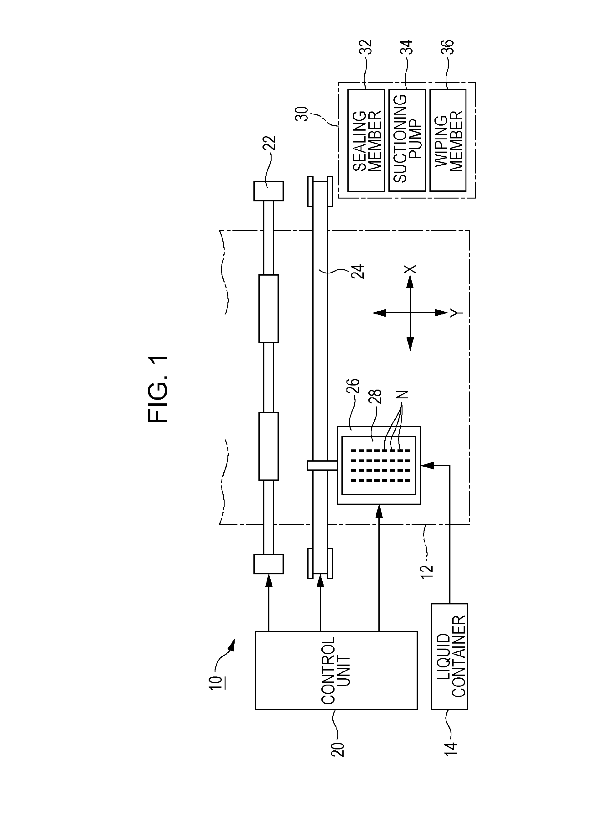
[0026]FIG. 1 is a configuration diagram of a liquid ejecting apparatus 10 according to a first embodiment of the invention. The liquid ejecting apparatus 10 according to the first embodiment is an ink jet printing apparatus which ejects ink as an example of liquid to a medium 12. A liquid container 14 which stores ink is mounted on the liquid ejecting apparatus 10. According to the first embodiment, a case in which solvent ink with a high weather resistance is ejected onto the medium 12 of a non-absorption type such as polyvinyl chloride is exemplified. The solvent ink is ink which is obtained by dispersing a color material such as a pigment or dye in various solvents such as an oil solvent (for example, diethylene glycol compound such as diethylene glycol diethyl ether), or an aqueous solvent, and conductivity thereof is sufficiently low compared to normal water based ink.

[0027]As illustrated in FIG. 1, the liquid ejecting apparatus 10 is provided with a control unit 20, a transpor...

second embodiment

[0042]A second embodiment of the invention will be described. In each form which will be exemplified below, elements with the same operation or function as that in the first embodiment will be given the same reference numerals which are used in descriptions of the first embodiment, and detailed descriptions thereof will be appropriately omitted.

[0043]FIG. 5 is a plan view and a sectional view in which a nozzle face 52 in the second embodiment is enlarged. As illustrated in FIG. 5, a plurality of nozzles N are formed along the Y direction on the nozzle face 52 in the second embodiment. A second region A2 is formed in a linear shape which extends in the Y direction so as to be continuous over two nozzles N which are adjacent to each other in the Y direction.

[0044]The same effect as that in the first embodiment is obtained also in the second embodiment. In addition, since the second region A2 which is continuous over two nozzles N which are adjacent to each other is formed in the secon...

third embodiment

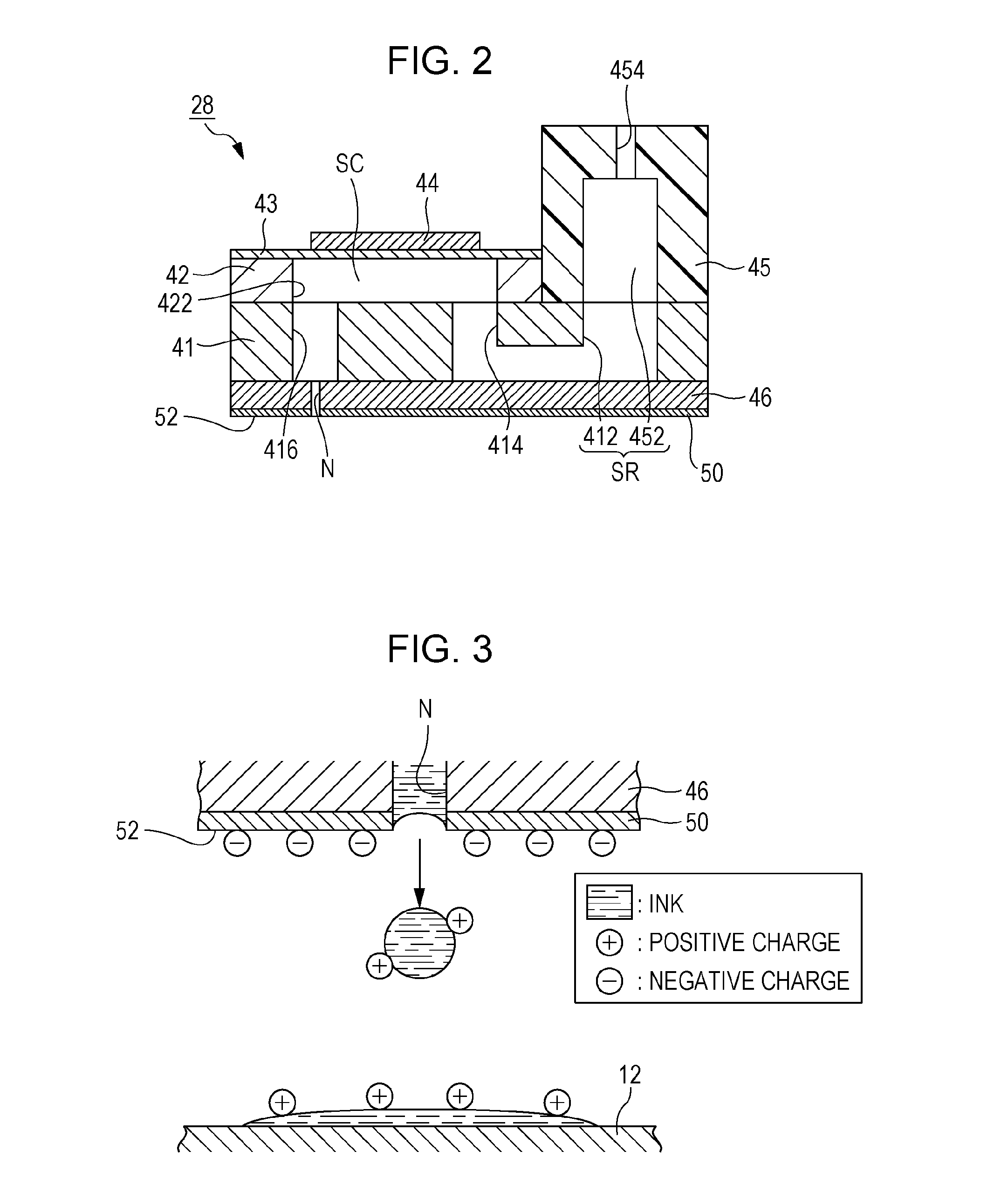
[0045]FIG. 6 is a diagram for explaining a relationship between air flow (hereinafter, referred to as “air current”) along the nozzle face 52 of the liquid ejecting head 28 and ejecting of ink. In a configuration in which a carriage 26 on which the liquid ejecting head 28 is mounted reciprocate in the X direction, an air current in the X direction is generated in the vicinity of the nozzle face 52. Accordingly, ink ejected from the nozzle N moves in a direction which is inclined to the X direction with respect to a Z direction (that is, vertical direction) which is perpendicular to the nozzle face 52, as denoted by a dashed line in FIG. 6, due to an influence of the air current which goes along the X direction, and as a result, there is a possibility that an error occurs in a landing position on the surface of the medium 12. In a viewpoint of reducing the error in the landing position by setting a movement direction of ink after being ejected to be close to the Z direction, it is de...


PUM


Abstract

A liquid ejecting head includes a nozzle face on which nozzles which eject liquid onto a medium are formed; a first region with a liquid repelling property which is connected to a peripheral edge of the nozzle when planarly viewed; and a second region with a liquid repelling property lower than that in the first region, which is connected to a peripheral edge of the nozzle when planarly viewed.

Description

BACKGROUND[0001]1. Technical Field[0002]The present invention relates to a technology of ejecting liquid such as ink.[0003]2. Related Art[0004]In a liquid ejecting head which ejects liquid such as ink from a plurality of nozzles which are formed on a nozzle face, there is a problem in that part of liquid (for example, fine liquid droplets which are misty) ejected from the plurality of nozzles is attached to the nozzle face. In order to solve the problem, for example, in JP-A-2007-331127, a configuration in which a voltage is applied between a liquid-repellent layer which surrounds each nozzle over the entire periphery thereof and a portion with no liquid-repellent processing in which liquid-repellent processing is not performed has been disclosed.[0005]Incidentally, since a fluorine-based liquid-repellent layer which is located on a negative side on a charging column, for example, is easy to be charged with a negative polarity, there is a case in which ink ejected from a nozzle is c...

Claims


Application Information

Patent Timeline
Patent Type & Authority Applications(United States)
IPC IPC(8): B41J2/14
CPCB41J2/1433B41J2/14314B41J2/14233B41J2/1606
Inventor OZAWA, KINYA
Owner SEIKO EPSON CORP
Why Eureka
Try Eureka