
Inverted-F antenna

a technology of inverted antennas and antennas, applied in the direction of elongated active element feeds, resonant antennas, antenna earthings, etc., can solve the problems of difficult design of planar antennas that offer performance comparable, energy conducted away from antennas, poor performance, etc., to reduce form factors and minimize mutual interference

Inactive Publication Date: 2005-05-17
KYOCERA CORP
View PDF5 Cites 46 Cited by
  • Summary
  • Abstract
  • Description
  • Claims
  • Application Information

AI Technical Summary

Benefits of technology

The present invention introduces an improved inverted-F antenna that has a reduced form factor and minimizes mutual interference with another antenna. The coplanar PIFA and coupled-feed PIFA offer this advantage. The coupled-feed PIFA allows for a connection to a transceiver using a conventional coaxial type connector. The coplanar and coupled-feed aspects can be combined. The antenna includes a transmission line port, an open radiator, a shorted "L" shaped radiator, and a groundplane. The shorted radiator is terminated in the transmission line port ground interface. The coplanar inverted-F antenna has an open radiator oriented in a first plane and a shorted "L" shaped radiator oriented in the first plane, connected to the open radiator and having a terminated end. The coplanar antenna also includes a feed oriented in the first plane and connected between the transmission line port signal interface and the open and shorted radiators. The groundplane is also oriented in the first plane. The shorted radiator is terminated in the transmission line port ground interface. The technical effects of the invention are improved performance and reduced interference between antennas.

Problems solved by technology

However, the antenna can have a fairly large form factor and, when seated in the chassis (contracted), performance is poor.
However it is difficult to design a planar antenna that offers performance comparable to that of a whip antenna, in particular as far as the bandwidth characteristics of the device are concerned.
Loss in an antenna is generally due to two sources: radiation, which is required; and energy that is conducted away from the antenna, which is undesirable.
Planar antennas have an undesirably low impedance bandwidth.

Method used


Image

  • Inverted-F antenna
  • Inverted-F antenna
  • Inverted-F antenna

Examples


Embodiment Construction

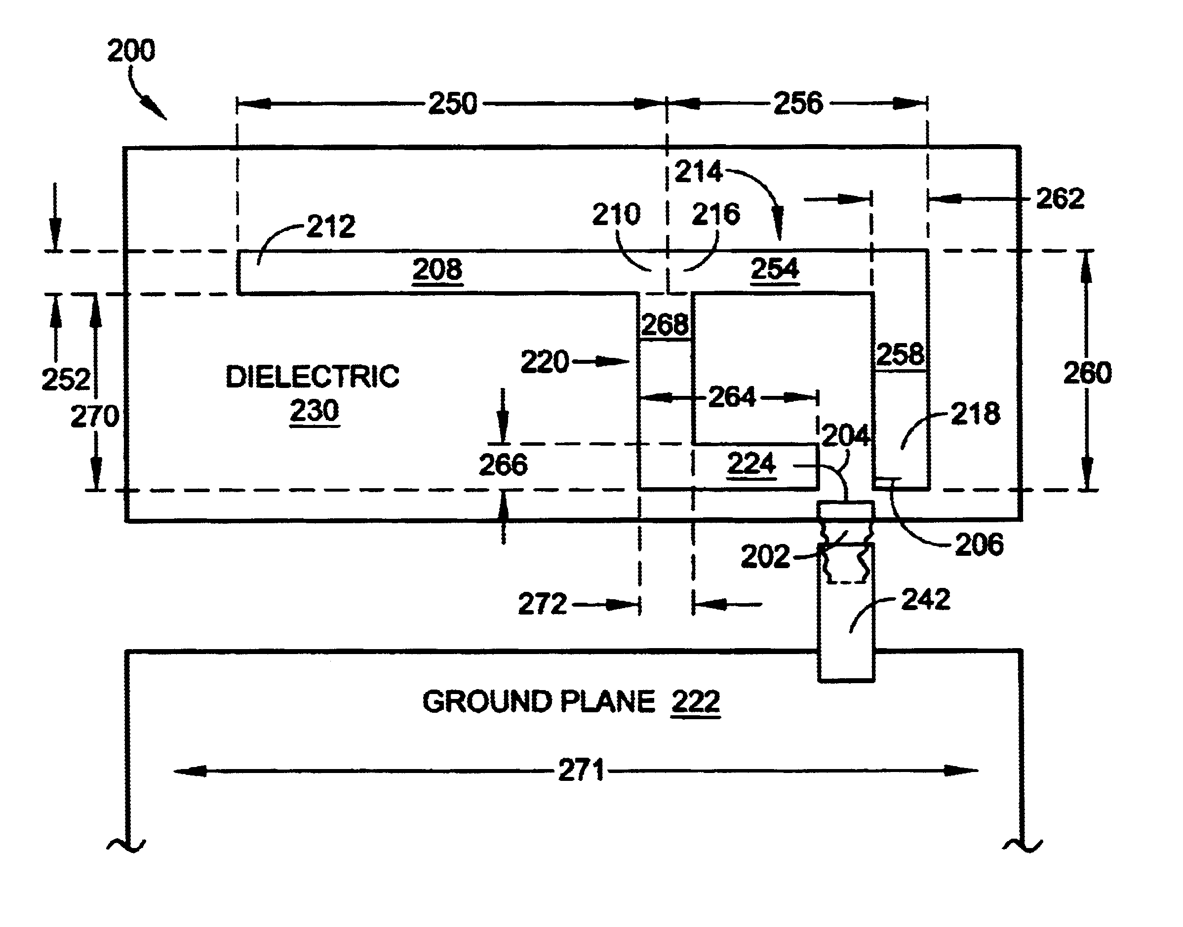
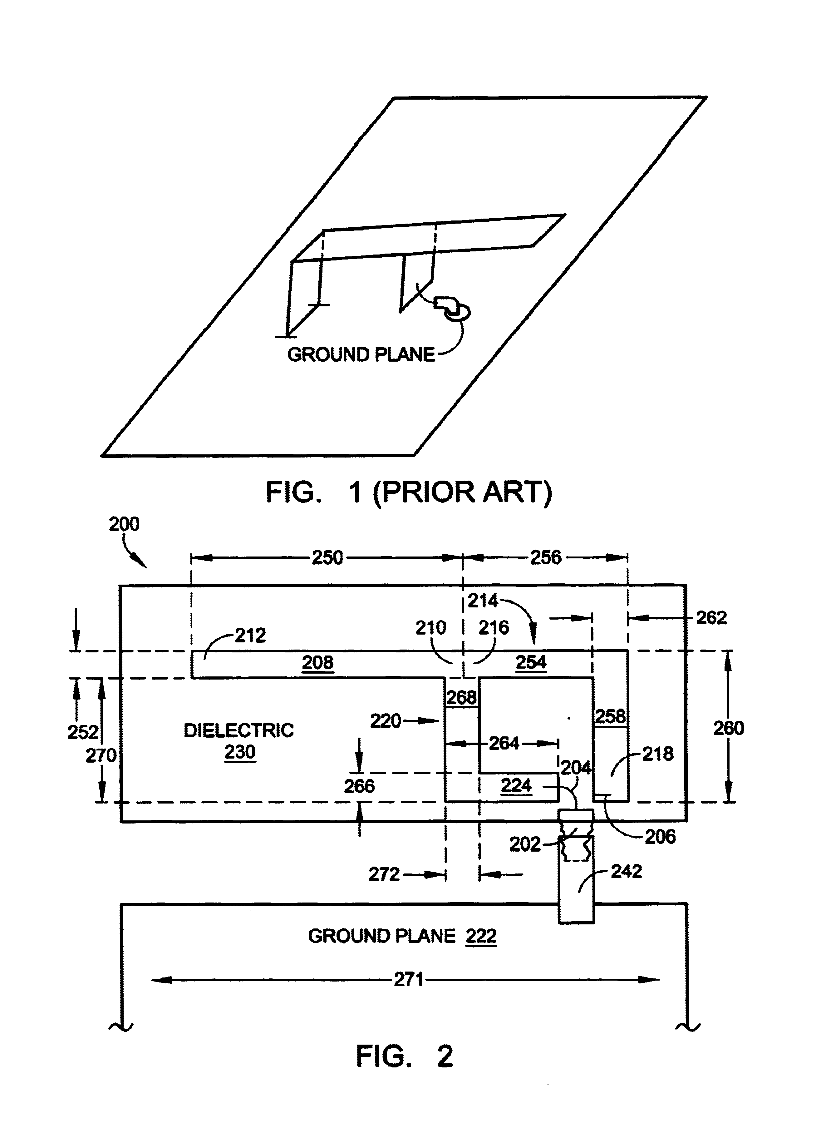
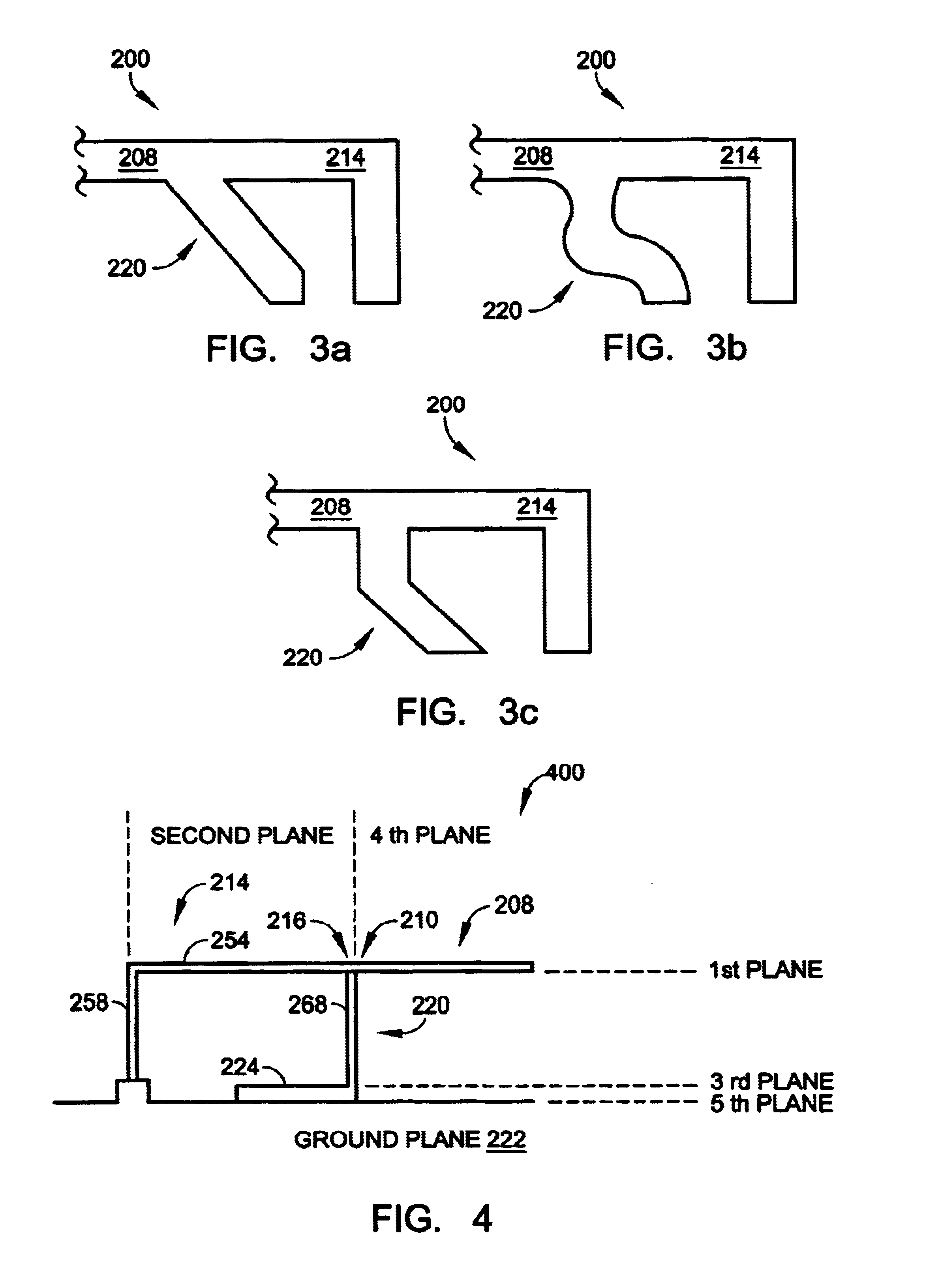
[0024]FIG. 2 is a plan view depicting the present invention coupled-feed inverted-F antenna. The coupled-feed PIFA 200 comprises a transmission line port 202 including a signal interface 204 and a ground interface 206. Conventionally, the impedance relationship between the signal interface 204 and the ground interface is 50 ohms, however, other impedances are possible. An open radiator 208 has a first end 210 and a second, unterminated end 212. A shorted “L” shaped radiator 214 has a first end 216, connected to the open radiator first end 210, and a second, terminated end 218. A coupled-feed 220 is connected between the transmission line port signal interface 204, and the open radiator first end 210 and the shorted radiator first end 216. That is, the coupled-feed 220 meets the radiator at the junction between the open radiator first end 210 and shorted radiator first end 216.

[0025]The coupled-feed antenna 200 also includes a groundplane. FIG. 2 depicts a groundplane 222 that is cop...


PUM


Abstract

A coupled-feed inverted-F antenna is provided comprising a transmission line port, an open radiator with an unterminated end, a shorted “L” shaped radiator connected to the open radiator with a terminated end, a coupled-feed connected between the transmission line port signal interface and the open and shorted radiators, and a groundplane. The coupled-feed is oriented parallel to the open radiator. A coplanar inverted-F antenna is provided comprising a transmission line port, an open radiator oriented in a first plane, a shorted “L” shaped radiator oriented in the first plane connected to the open radiator and having an terminated end, a feed oriented in the first plane and connected between the transmission line port signal interface and the radiators, and a groundplane oriented in the first plane. The shorted radiator is terminated in the transmission line port ground interface. The antenna may also employ both coplanar and coupled-feed features.

Description

RELATED APPLICATIONS[0001]This application is related to application Ser. No. 10 / 120,603, entitled, INVERTED-F FERROELECTRIC ANTENNA, invented by Jorge Fabrega-Sanchez, Stanley S. Toncich and Alan Tran, filed Apr. 9, 2002, now abandoned, which is hereby incorporated by reference.BACKGROUND OF THE INVENTION[0002]1. Field of the Invention[0003]This invention generally relates to wireless communication antennas and, more particularly, to an improved inverted-F antenna including coplanar and coupled-feed features.[0004]2. Description of the Related Art[0005]Many conventional wireless communications devices, such as a wireless telephone, uses a whip antenna. The whip propagates excellently, when deployed (extended) from the device chassis. However, the antenna can have a fairly large form factor and, when seated in the chassis (contracted), performance is poor. A smaller, internally mounted, antenna is desirable. One such antenna is the so-called inverted-F antenna.[0006]FIG. 1 is a depi...

Claims


Application Information

Patent Timeline
Patent Type & Authority Patents(United States)
IPC IPC(8): H01Q9/04H01Q1/24
CPCH01Q1/243H01Q9/42H01Q9/0442H01Q9/0421
Inventor JENWATANAVET, JAY
Owner KYOCERA CORP
Learn More