Heating device suitable for motor vehicles

a motor vehicle and heating device technology, applied in the direction of domestic stoves or ranges, fluid friction heating, lighting and heating apparatus, etc., can solve the problem of increasing the production cost of heating devices

Inactive Publication Date: 2005-05-24
BEHR GMBH & CO KG
View PDF13 Cites 11 Cited by
  • Summary
  • Abstract
  • Description
  • Claims
  • Application Information

AI Technical Summary

Benefits of technology

[0005]It is also an object of the invention to provide an improved method for controlling the heat output of a drive power source in a motor vehicle.

Problems solved by technology

The axially movable arrangement of the rotor on the drive shaft, which requires a corresponding linear bearing, entails a structural outlay that increases the production costs of a heating device of this type, which is produced in large series for motor vehicles.

Method used


Image

  • Heating device suitable for motor vehicles
  • Heating device suitable for motor vehicles
  • Heating device suitable for motor vehicles

Examples


Embodiment Construction

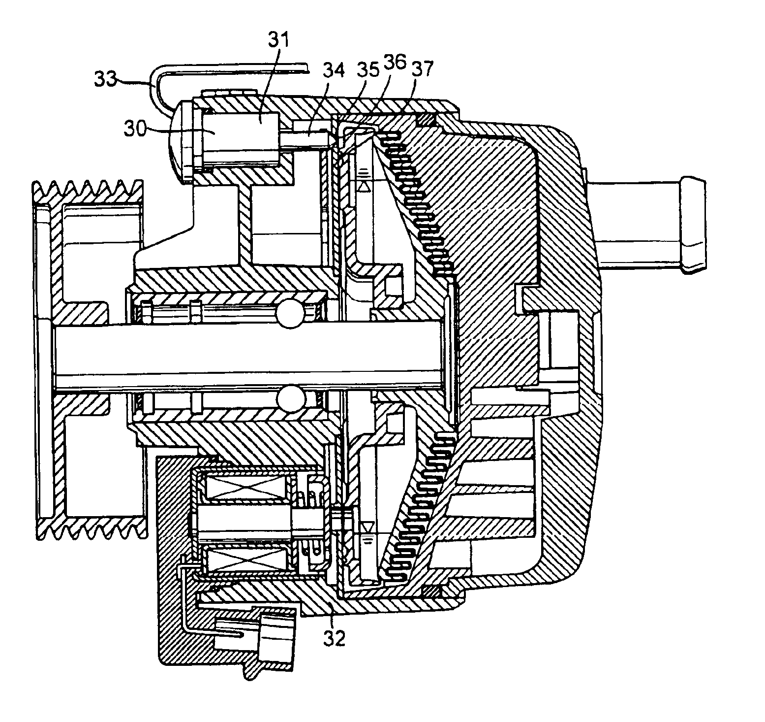
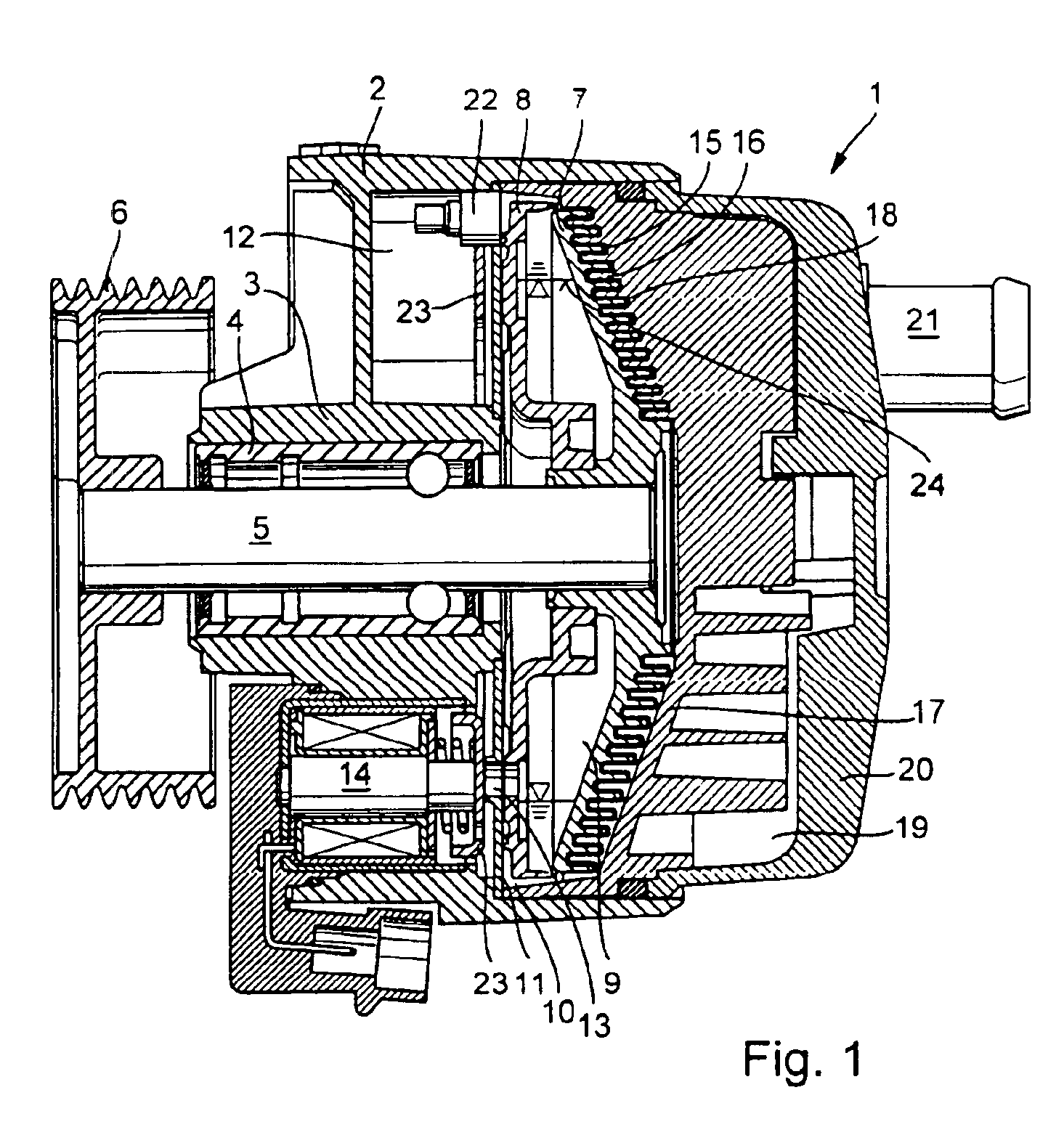
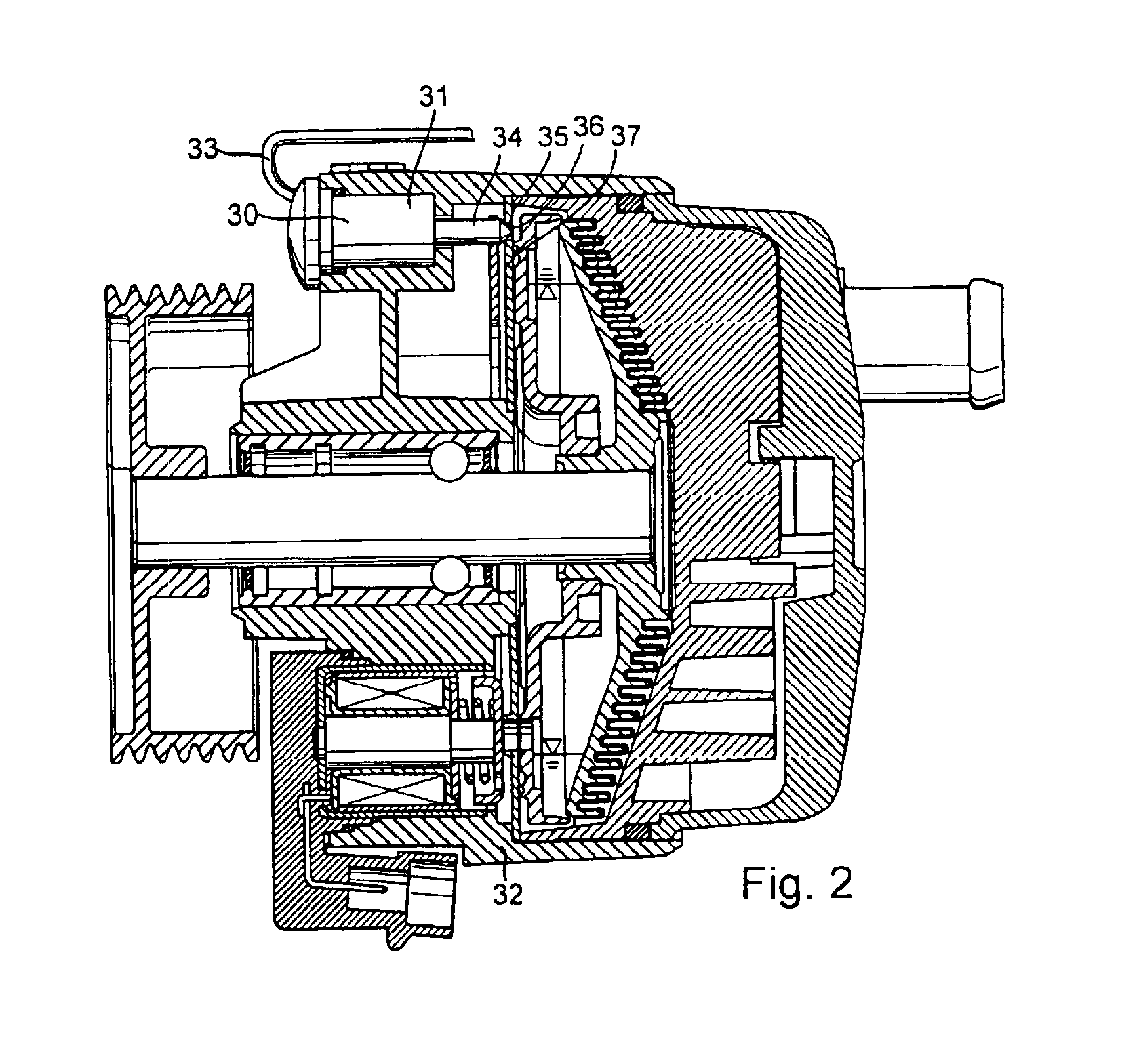
[0016]According to the invention, a control valve is arranged in the return part of the viscous liquid circuit in the heating device. This relatively simple design measure allows the pressure of the viscous liquid in the working chamber and therefore also in the working gap to be controlled, which at the same time results in the heating output being controlled. A linear bearing, which is subject to wear, can be dispensed with, since the rotor is arranged fixedly on the drive shaft in the axial direction. Overheating, which could even lead to the viscous liquid being destroyed, is avoided. Furthermore driving output of the internal combustion engine of the motor vehicle is also saved, since the drive moment required for the rotor is reduced with the reduction in pressure. This measure is based on the discovery that the static pressure of the viscous liquid in the working space and therefore also in the working gap is important for the torque which can be transmitted and therefore als...


PUM


Abstract

The invention relates to a heating device, in particular for motor vehicles, for generating frictional heat by liquid friction with a housing which is arranged in a stationary position and has a working space and a motor-driven rotor in the working space.

Description

CROSS-REFERENCE TO RELATED PATENT APPLICATIONS[0001]The right of priority under 35 U.S.C. §119(a) is claimed based on German Patent Application No. 101 44 845.7, filed Sep. 6, 2001, the entire disclosure of which is hereby incorporated by reference.BACKGROUND OF THE INVENTION[0002]The invention relates to a heating device, in particular for a motor vehicle, for generating frictional heat by liquid friction.[0003]A heating device of this general type is disclosed by DE-A 198 27 097, which is commonly assigned with the present application. This known heating device is an auxiliary heater for motor vehicles with consumption-optimized engines, in which, therefore, there is relatively little waste heat available from the engine for heating purposes. In the known design, the heating warmth is generated via liquid friction and is dissipated to the coolant of the engine. A rotor which rotates in a working space of the heating device is driven by the internal combustion engine of the motor v...

Claims


Application Information

Patent Timeline
Patent Type & Authority Patents(United States)
IPC IPC(8): B60H1/02B60H1/14F24J3/00
CPCB60H1/038F24J3/003B60H1/14B60H2001/146F24V40/00
Inventor AUGENSTEIN, CLAUSGRAMLICH, ARMINKAMSIZ, OEZGUERLINDAUER, KUNOMAUS, RALF
Owner BEHR GMBH & CO KG
Why Eureka
Try Eureka