Mounting element and method of manufacturing the same

a technology of mounting elements and manufacturing methods, applied in the direction of screws, fastening means, washers, etc., can solve the problems of affecting the operation of the cam, so as to simplify and save the operation. , the effect of eliminating the disadvantages

Inactive Publication Date: 2005-05-24
NORD LOCK AB (SE)
View PDF12 Cites 32 Cited by
  • Summary
  • Abstract
  • Description
  • Claims
  • Application Information

AI Technical Summary

Benefits of technology

[0010]The present invention intends to eliminate the aforesaid disadvantages according to the prior art described above. The object is also to produce a mounting element comprising several components of the type where included pairs of washers have cams only on the sides facing each other and which components are held together in one unit. Another intention is to produce a mounting element that is simplified and economical from a manufacturing point of view.

Problems solved by technology

If washers are fitted incorrectly or turned the wrong way around, or if the wrong washers are used, this will cause the cam actuated locking function to fail so that the nut can easily come loose if e.g. subjected to vibration.
Control of the tension will also be lost.
Without teeth on the washer, there is a risk that friction when unscrewing is lowest between the surface and the washer.
This means that the cam actuated locking will not work and the nut can come loose if subjected to vibration.
When fitting a mounting element, it is awkward to have several loose and separate components that must be applied together, especially if the actual fitting of the mounting element on the surface must be done in places that are difficult to access.
From the point of view of handling, it is also a disadvantage to have to keep track of and manage several loose components.
It is also known to have a lower washer with a high outside flange, where the flange is upset after fitting the component parts of the nut.
This is a complicated method of manufacture and is economically disadvantageous.

Method used


Image

  • Mounting element and method of manufacturing the same
  • Mounting element and method of manufacturing the same
  • Mounting element and method of manufacturing the same

Examples


Embodiment Construction

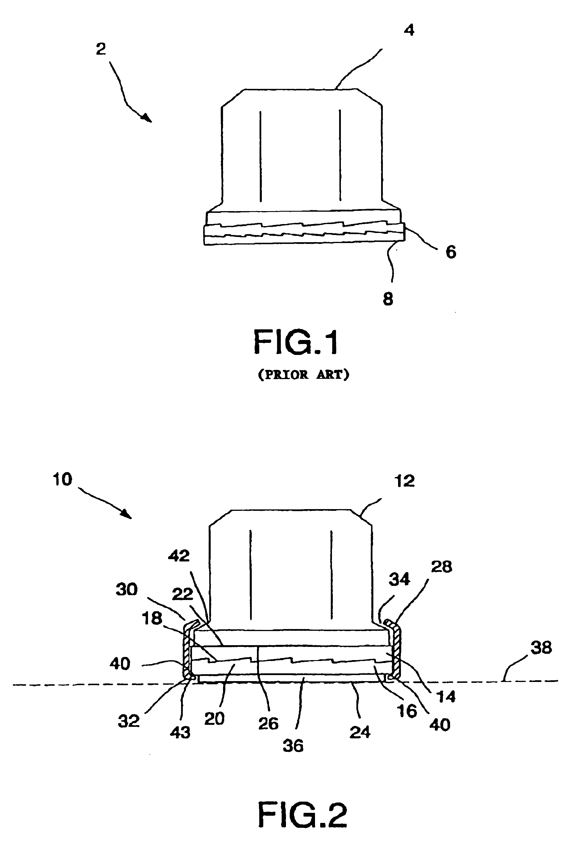
[0022]FIG. 1 shows a mounting element 2 according to prior art comprising a washer 6 closest to a nut 4. The nut 4 and the upper washer 6 both have cams facing each other. The washer 6 has cams on both sides with a lower washer 8 with cams on one side facing the upper washer 6. When tightening, the washer 6 slides over the cams on washer 8. In case of vibration, washer 6 and nut 4 can rotate on washer 8 if the friction between the upper washer and the lower washer is less than the friction between the nut and the upper washer. This will reduce the tension.

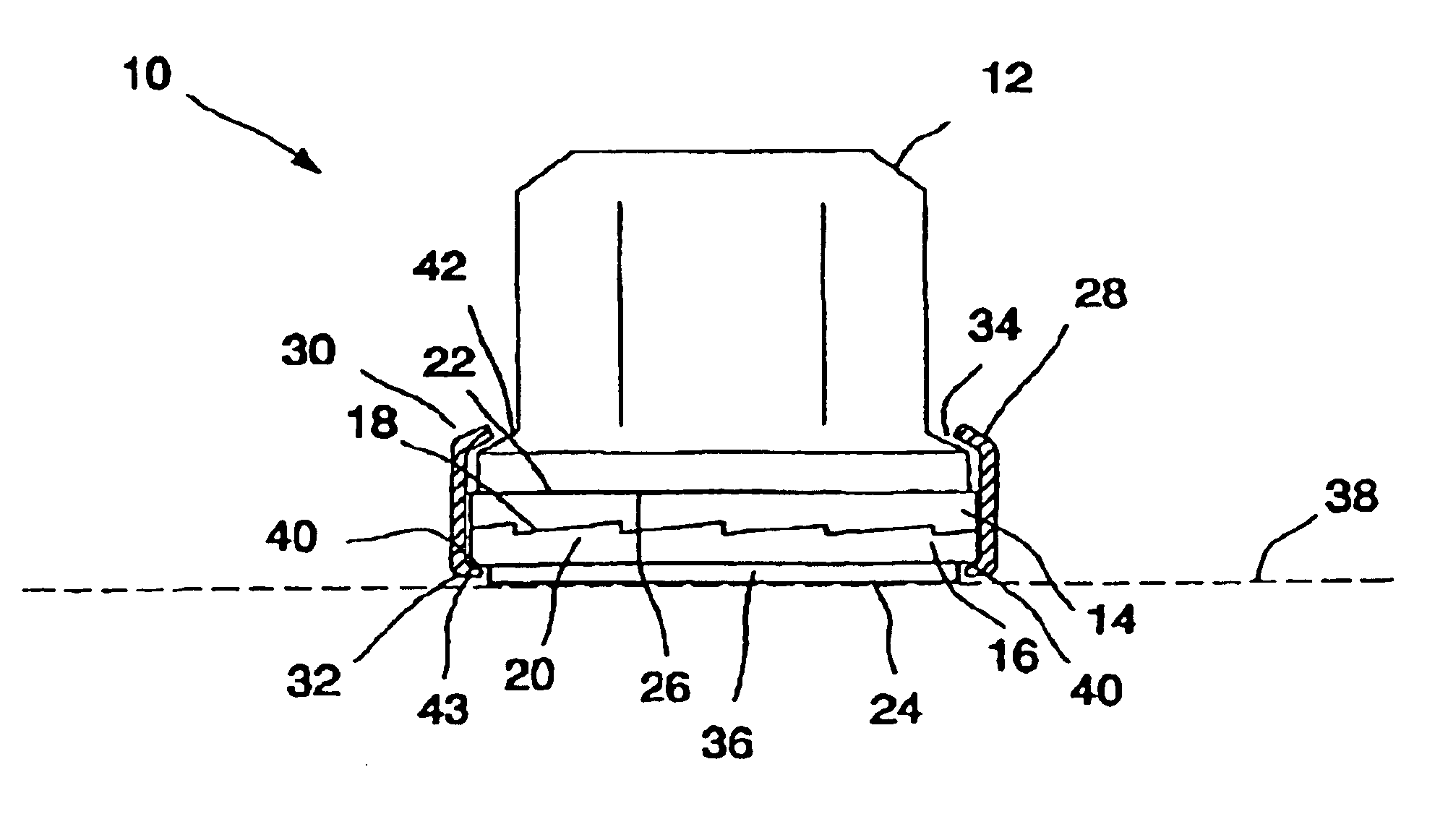
[0023]FIG. 2 shows a mounting element 10 according to the present invention comprising a means of fastening 12, here shown in the form of a flange nut, an upper washer 14 and a lower washer 16, which both constitute a pair of washers. Each washer 14, 16 has one side with cams 18, 20 and one principally flat side 22, 24, the washer sides with cams being arranged facing each other. The means of fastening 12 comprises one principally ...


PUM


Abstract

The present invention concerns a mounting element (2, 10, 50, 1000) comprising a means of fastening (4, 12, 53, 102) such as a nut or bolt and an upper washer (14) and a lower washer (16) constituting a pari of washers, where each washer has one side with cams (18, 20) and one principally flat side (22, 24), the washer sides with cams being arranged facing each other. Moreover, the means of fastening includes a principally flat side (26) arranged against a principally flat upper side (22) of the upper washer (14). The said mounting element furthermore includes at least one means of containment (28) arranged to keep together the means of fastening and the pair of washers, whereby the means of containment is allowed a certain axial movement and rotation in relation to the means of fastening or the movement of the pair of washers. The present invention concerns also a means of manufacturing a mouting element and a usage.

Description

BACKGROUND OF THE INVENTION[0001]1. Technical Field[0002]The present invention concerns a mounting element comprising a means of fastening such as a nut or a bolt. The present invention concerns also a means of manufacturing a mounting element.[0003]2. Description of the Background Art[0004]In connection with the use of a means of fastening such as nuts and bolts, other components such as washers are often also used to provide an enhanced securement of the means of fastening. The present invention is aimed at the type of mounting element that includes a means of fastening such as a nut or bolt that utilizes an upper and a lower washer. The washers form a pair, where each washer has one side with tags thereon that are used facing each other. Each tagged side fits against the tagged side of the corresponding washer. The other side of each washer is principally flat. The means of fastening has also a principally flat side arranged against the principally flat and smooth upper side of t...

Claims


Application Information

Patent Timeline
Patent Type & Authority Patents(United States)
IPC IPC(8): F16B39/282F16B39/00
CPCF16B39/282
Inventor ANDERSSON, MATTIAS
Owner NORD LOCK AB (SE)
Why Eureka
Try Eureka