
Cable assembly with power adapter

a technology of power adapter and cable connector, which is applied in the direction of coupling device details, electrical discharge lamps, coupling device connections, etc., can solve the problems of inconvenient and expensive formation of two separate connectors

Inactive Publication Date: 2005-05-24
HON HAI PRECISION IND CO LTD
View PDF9 Cites 35 Cited by
  • Summary
  • Abstract
  • Description
  • Claims
  • Application Information

AI Technical Summary

Benefits of technology

[0009]Accordingly, an object of the present invention is to provide a cable assembly having a cable connector and a power adapter respectively for signal and power transmission with inlayed bolts.

Problems solved by technology

However, in some particular circumstances, the two matable Serial ATA power connectors of the pair of cable assemblies do not directly mate with each other.
However, forming the two separate connectors is expensive and inconvenient compared to the formation of a unitary member which can perform the functions of signal and power transmission.

Method used


Image

  • Cable assembly with power adapter
  • Cable assembly with power adapter
  • Cable assembly with power adapter

Examples


Embodiment Construction

[0020]Reference will now be made in detail to the preferred embodiment of ent invention.

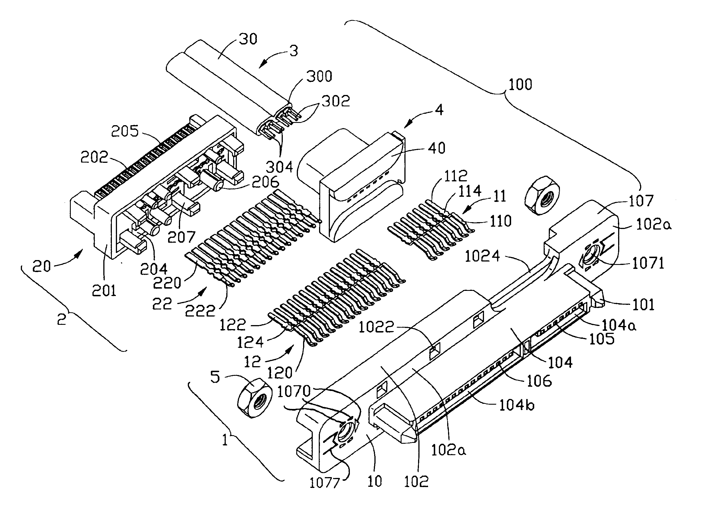
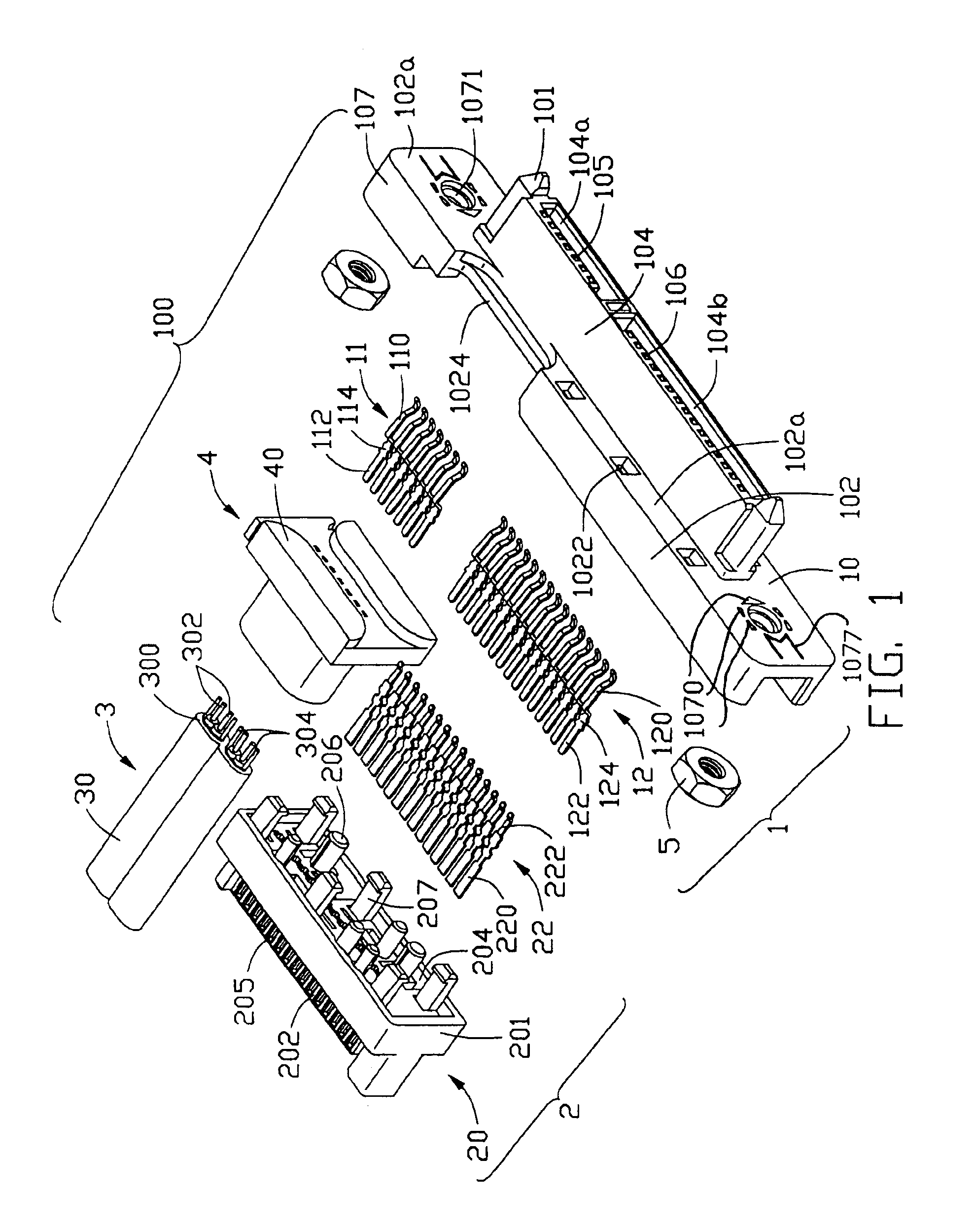
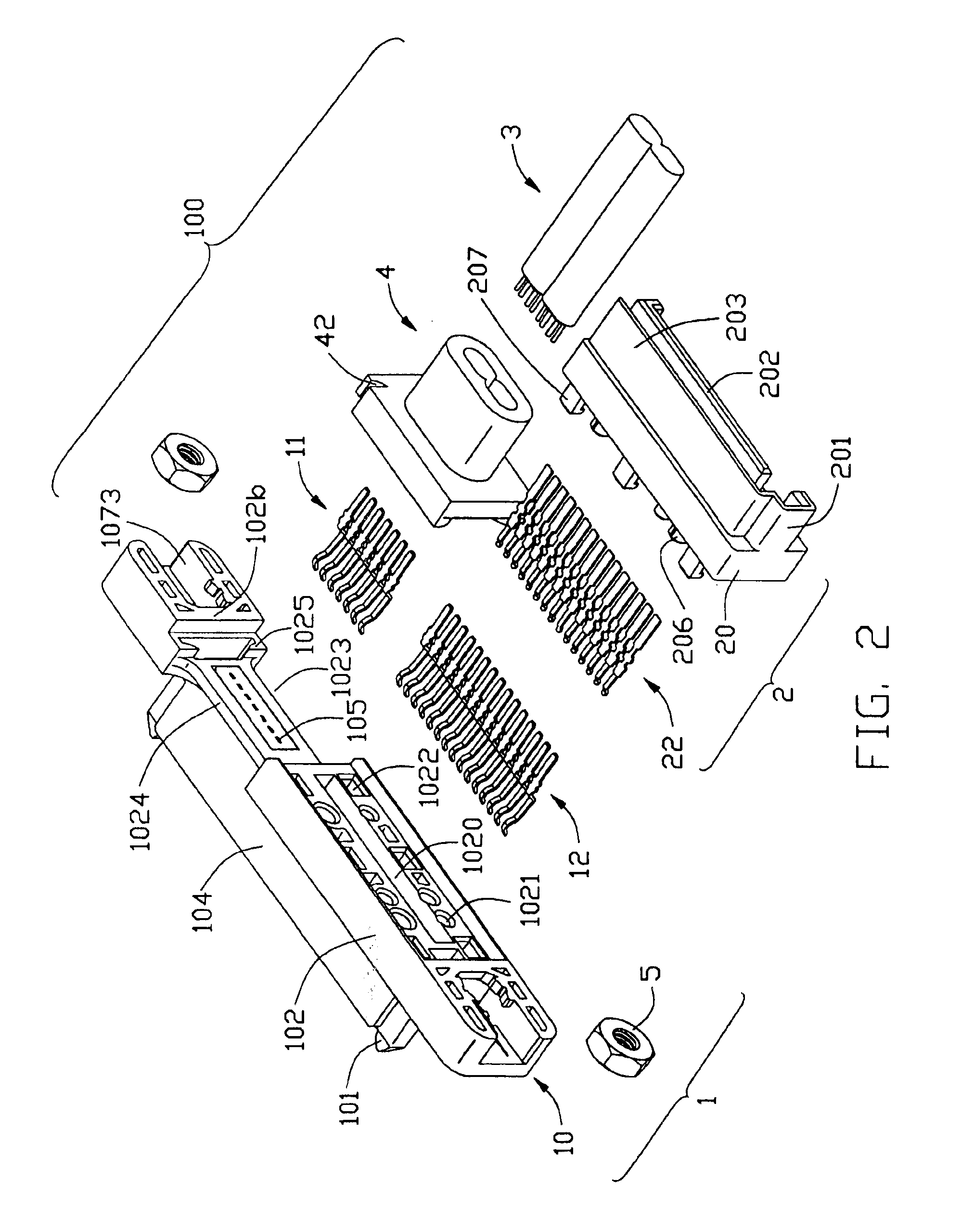
[0021]Referring to FIGS. 1-3, a cable assembly 100 in accordance with the invention comprises a first connector 1, a second connector 2 back to back ed to the first connector 1, a cable 3 terminated to the first connector 1 and a cover 4 overmolded with the cable 3 and the first connector 1. In a preferred embodiment, the first connector 1 is a Serial Advanced Technology Attachment (Serial ATA) receptacle connector. The second connector 2 is a Serial ATA plug connector. The cable 3 is a Serial ATA cable.

[0022]The first connector 1 comprises a first insulating housing 10, a plurality of first and second receptacle contacts 11, 12 retained in the first housing 10, and a pair of screw caps 5 assembled to the first insulating housing 10. The first housing 10 has an elongate base 102 and a mating section 104 extending perpendicularly and forwardly from a front face 102a of the base 102. A pair of guid...


PUM


Abstract

A cable assembly (100) includes a first connector (1) including a first insulating housing (10) extending in a lengthwise direction and a number of first and second contacts (11, 12) received in the first housing in a lateral direction perpendicular to the lengthwise direction, a cable (3) including a number of conductors (302, 304) electrically connecting with the first contacts, a second connector including a second housing (20) back to back assembled to the first housing and a number of third contacts (22) electrically connecting with the second contacts of the first connector, and a pair of screw caps (5). The first insulating housing defines a pair of fitting spaces (1073) extending in the lengthwise direction and a pair of mounting holes (1071) extending in the lateral direction and respectively communicating with the fitting spaces, and the pair of screw caps are respectively received in the fitting spaces in the lengthwise direction.

Description

CROSS-REFERENCE TO RELATED APPLICATIONS[0001]This patent application is related to U.S. patent application Ser. Nos. 10 / 385,794 filed on Mar. 10, 2003 and entitled “ELECTRICAL ADAPTER”, 10 / 668,739 filed on Sep. 23, 2003 and entitled “CABLE ASSEMBLY WITH POWER ADAPTER”, both of which are invented by the same inventor and assigned to the same assignee as this application.BACKGROUND OF THE INVENTION[0002]1. Field of the Invention[0003]The present invention relates to a cable assembly, and particularly to a cable assembly having a cable connector and a power adapter respectively for signal and power transmission.[0004]2. Description of Related Art[0005]In recent days, an electrical connector known as a Serial Advanced Technology Attachment (Serial ATA) connector, according to the newly developed Serial ATA interface standard, is developed to be generally used for connecting storage peripheral devices such as hard disk drives with a mother printed circuit board so as to achieve signal or...

Claims


Application Information

Patent Timeline
IPC IPC(8): H01R31/06H01R13/74H01R27/00H01R27/02
CPCH01R31/06H01R13/748H01R27/02
Inventor WU, JERRY
Owner HON HAI PRECISION IND CO LTD
Learn More