
System and related methods for sensing forces on a movable barrier

a technology of sensing force and movable barrier, which is applied in the direction of motor/generator/converter stopper, dynamo-electric converter control, instruments, etc., can solve the problems of affecting the speed of the door, the inability of the pulse counter to accurately keep count, and the inability of the microprocessor to also lose coun

Inactive Publication Date: 2005-05-24
HOMERUN HLDG
View PDF19 Cites 39 Cited by
  • Summary
  • Abstract
  • Description
  • Claims
  • Application Information

AI Technical Summary

Problems solved by technology

Unfortunately, pulse counters cannot accurately keep count.
External factors such as power transients, electrical motor noise, and radio interference often disrupt the count, allowing the door to over-travel or under-travel.
The microprocessor may also lose count if power to the operator is lost or if the consumer manually moves the door while the power is off and the door is placed in a new position that does not match the original count.
However, if the door encounters an obstacle during travel, the speed of the door slows down or stops, depending upon the amount of negative force applied by the obstacle.
However, due to the inertia and speed of the door and the tolerances in the door and track system, these internal entrapment systems are very slow to respond, and some time passes after contacting an obstruction before the internal entrapment device is activated, thus allowing the door to over-travel and exert very high forces on an object that is entrapped.
As such, known internal entrapment systems, by themselves do not work well, especially when the open / close cycle is remotely actuated.
In most instances, this length of time is much too long.
This type of internal entrapment systems is slow to respond due to the inertia of the door, the stretch in the drive belt or chain, and the components of the drive system.
However, due to aging of the door system and environmental conditions that can change the force required to move the door, these systems are normally adjusted to the highest force condition anticipated by the installer or the consumer.
Further, over time the clutch plates can corrode and freeze together, preventing slippage if an obstruction is encountered.
Therefore, the heavier the load, the slower the rotation of the motor.
As discussed previously, optical encoders and magnetic flux pickup sensors are susceptible to interference and the like.
As noted previously, out-of-balance conditions may not be fully considered in systems with an encoder.
Nor does the disclosed system consider an out-of-balance condition or contemplate that different speeds may be encountered at different positional locations of the door during its travel.
As discussed previously, the positional location of the door cannot be reliably and accurately determined by pulse counter methods.
Unfortunately, the typical trolley-type operator is not sensitive enough to provide adequate entrapment protection in that the operator is slow to respond when an obstruction is encountered, and secondary entrapment protection is provided to achieve improved protection.
These devices may have dead spots in areas that need detection beyond the range of individual sensors.
This can be corrected by adding additional sensors to cover the dead spot, but this adds to the cost of the protection system and to the cost of installation.
Additionally, these types of sensors require alignment to work properly and can become misaligned during use.
These sensors are also affected by moisture and dust on their lenses, preventing proper operation.
These switches must extend through or along the perimeter of the opening and will increase in cost proportional to the size of the opening.
Doors that are directly connected to the motorized unit, such as a garage door and a garage door operator, are not precise units due to the slack in the mechanical drive train and the methods of attaching to the door.
Moreover, the guide rails and the mountings can deflect when an obstruction is encountered, delaying or preventing standard sensors from indicating an obstruction.
As will be appreciated, this extensive wiring adds to the cost of installation and is susceptible to damage.
However, the strain gauge does not necessarily detect the force that the operator is applying to the arm.
This may lead to an inaccurate reading of force actually applied to the door and results in false readings.
And the strain gauge is a costly component.

Method used


Image

  • System and related methods for sensing forces on a movable barrier
  • System and related methods for sensing forces on a movable barrier
  • System and related methods for sensing forces on a movable barrier

Examples


Embodiment Construction

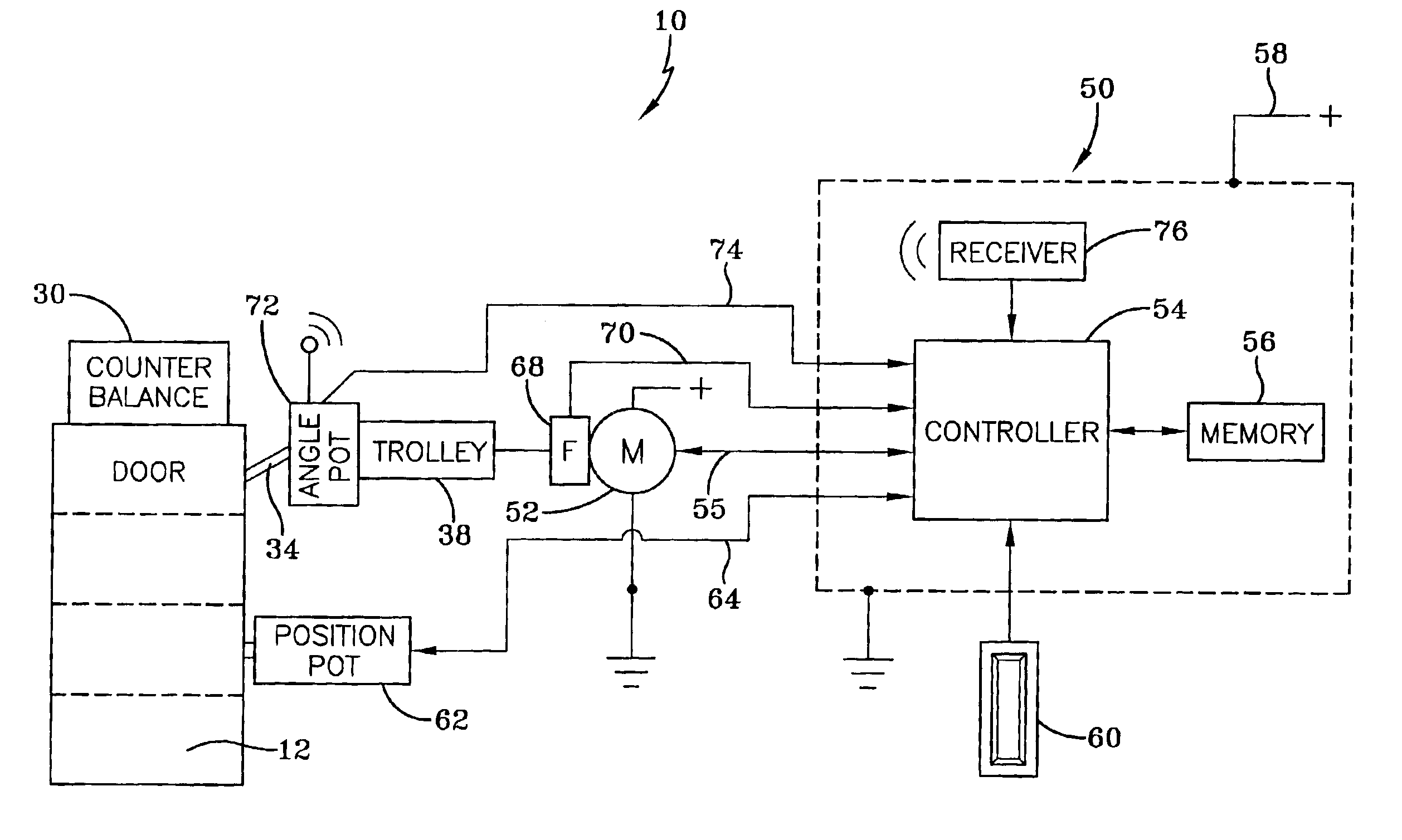
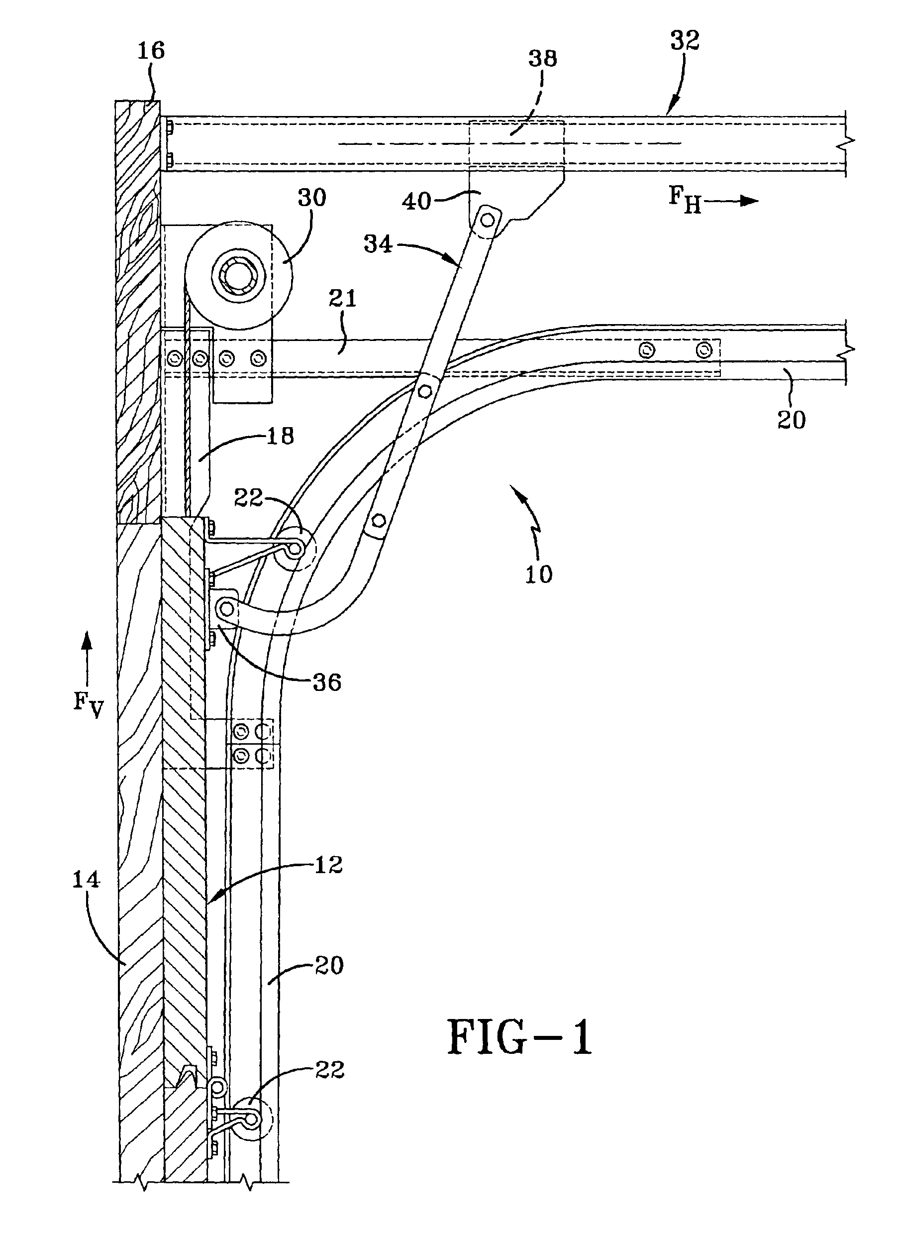
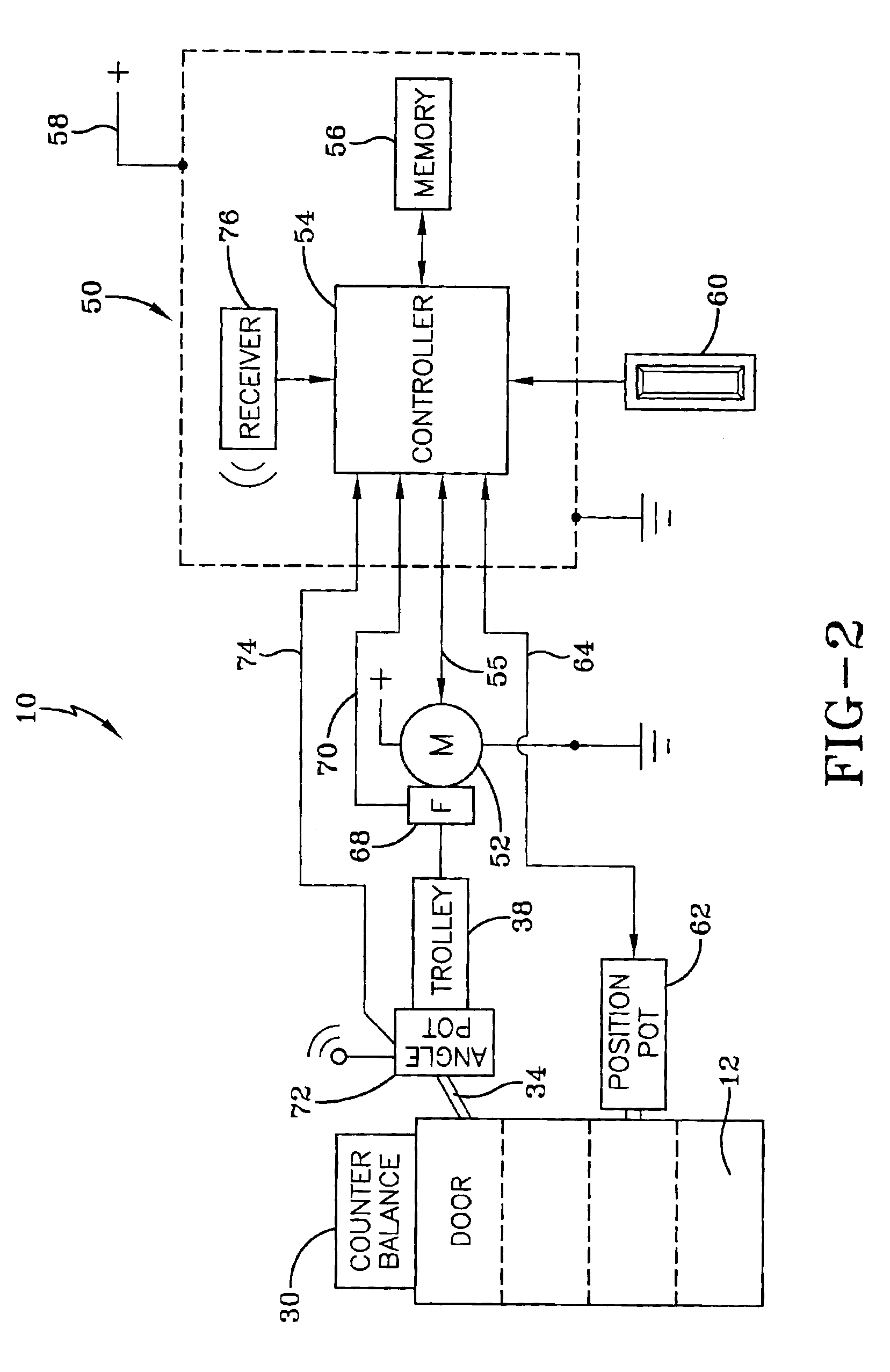
[0031]A system and related methods for sensing forces on a movable barrier is generally indicated by the numeral 10 in FIGS. 1 and 2. As best seen in FIG. 1, the system 10 is employed in conjunction with a conventional sectional garage door, generally indicated by the numeral 12. The present invention may also be employed for use with gates, windows, retractable awnings or other closures directly connected to a driving source such as a motorized operator. The opening in which the door 12 is positioned for opening and closing movements relative thereto is surrounded by a pair of vertically spaced jamb members 14, which are generally parallel and extend vertically upwardly from the ground (only one jamb member is shown). Jambs 14 are spaced apart and joined at their vertical upper extremity by a header 16 to thereby form a generally u-shaped frame around the opening of the door 12. The jamb members 14 and headers 16 are normally constructed of lumber or other structural building mater...


PUM


Abstract

An operator system and related methods (10) for sensing forces on a movable barrier (12) includes a motor (52), a trolley (30), and a trolley arm (34) having a first end slidably supported by the trolley (38) and a second end coupled to the movable barrier. The motor moves the trolley arm which in turn moves the movable barrier. A force detection mechanism (68) is coupled to the motor to determine a first component force value applied by the motor. A controller (54) receives the first component force value and determines a detected force value by scaling the first component force value with a second component force value derived from an angular position of the trolley arm's first end with respect to the trolley. The angular position of the trolley arm may be fixed or variable. An angle potentiometer (72) is coupled to the trolley arm to generate an angle signal for use as the second component force value when the trolley arm's angular position is allowed to vary.

Description

TECHNICAL FIELD[0001]Generally, the present invention relates to detecting and measuring the force applied to a door or any device that is directly connected to a trolley-type operator as the door travels between open and closed positions. In particular, the present invention relates to a system which utilizes the angle of a trolley arm to monitor the force applied to an overhead door during each cycle. Specifically, the present invention relates to a system that monitors the force applied and, along with other monitored data, determines if an obstruction has been encountered.BACKGROUND ART[0002]As is well known, motorized door operators automatically open and close a garage door or the like through a path that is defined by a physical upper limit and a physical lower limit. The physical lower limit is established by the floor upon which the garage door closes. The physical upper limit can be defined by the highest point the door will travel, which can be limited by the operator, th...

Claims


Application Information

Patent Timeline
IPC IPC(8): E05F15/00E05F15/16
CPCE05F15/41E05Y2400/326E05Y2400/554E05F15/668E05Y2900/106
Inventor MURRAY, JAMES S.BENNETT, III, THOMAS B.
Owner HOMERUN HLDG
Features
  • Generate Ideas
  • Intellectual Property
  • Life Sciences
  • Materials
  • Tech Scout
  • Unparalleled Data Quality
  • Higher Quality Content
  • 60% Fewer Hallucinations
Learn More