Spectral power equalizer for wavelength-multiplexed optical fiber communication links

a technology of optical fiber communication link and equalizer, applied in the field of optical communication, can solve the problems of overloading a receiver in the network, signal may also experience both transmission loss and coupling loss, and uneven amplifier amplification gain

Inactive Publication Date: 2005-05-24
JDS UNIPHASE CORP
View PDF10 Cites 10 Cited by
  • Summary
  • Abstract
  • Description
  • Claims
  • Application Information

AI Technical Summary

Benefits of technology

[0009]The present invention relates to an equalizer, and more specifically to a channel equalizer having a concave diffraction grating to diffract a multiplexed optical signal into a plurality of sub-beams of light and a modulator for receiv

Problems solved by technology

However, if a signal has too much power, it may overload a receiver in the network.
As signals propagate through the optical fiber, the signals may also experience both transmission losses and coupling losses at points along the network.
One problem with prior WDM networks is the amplification gain provided by the amplifiers may be uneven, such that certain wavelengths are amplified to a greater degree than other wavelengths.
Such non-uniformity in losses and gains accumulates and causes transmission errors in the form of interc

Method used


Image

  • Spectral power equalizer for wavelength-multiplexed optical fiber communication links
  • Spectral power equalizer for wavelength-multiplexed optical fiber communication links
  • Spectral power equalizer for wavelength-multiplexed optical fiber communication links

Examples


Embodiment Construction

[0025]In the following description, numerous specific details are set forth such as examples of specific materials, components, dimensions, etc. in order to provide a thorough understanding of the present invention. It will be apparent, however, to one skilled in the art that these specific details need not be employed to practice the present invention. In other instances, well known materials or methods have not been described in detail in order to avoid unnecessarily obscuring the present invention.

[0026]A method and apparatus is described for controlling the attenuation of multiple wavelength signals independently propagating in an optical fiber to provide an output signal having a desired attenuated power in each of the multiple signals.

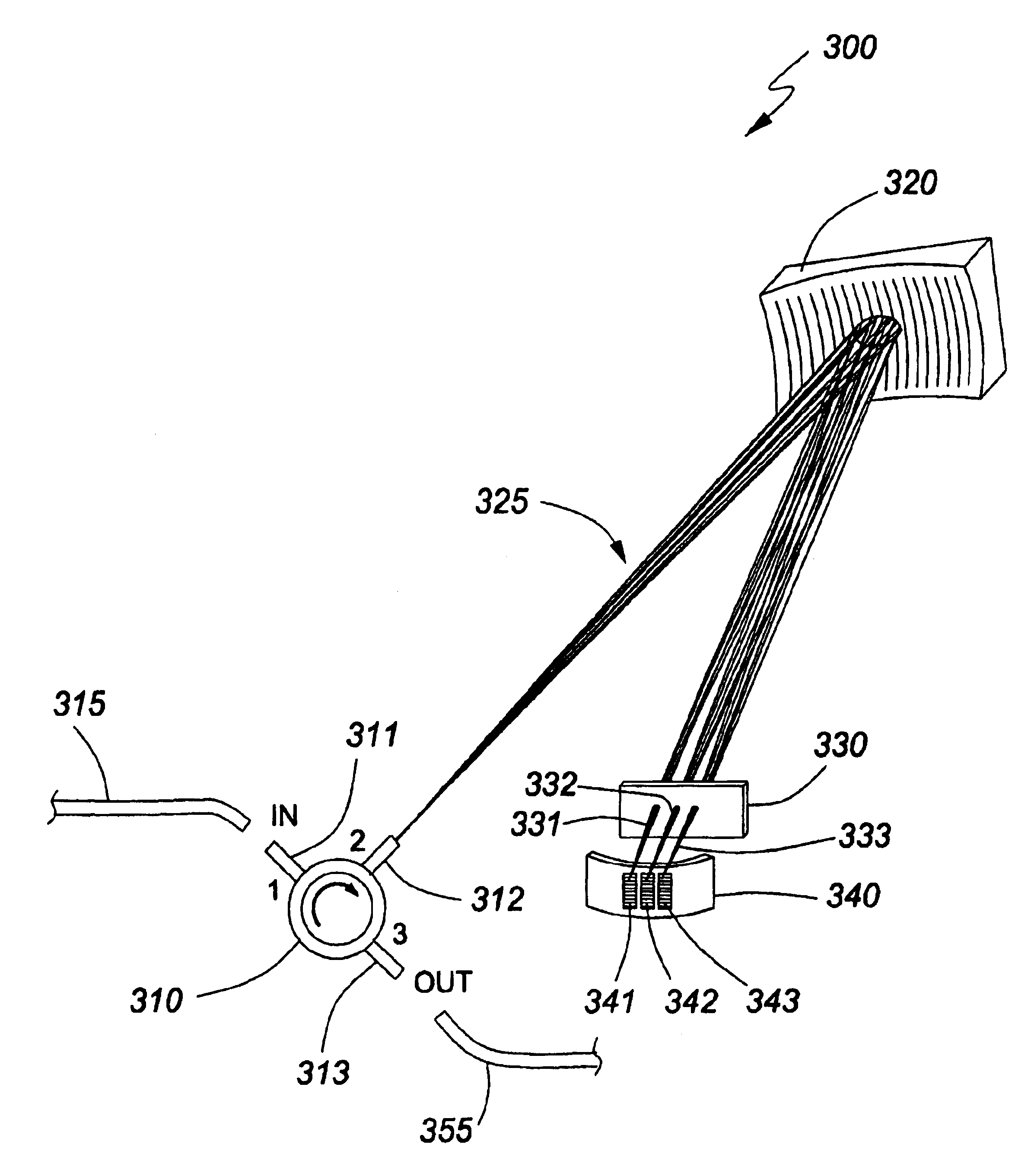
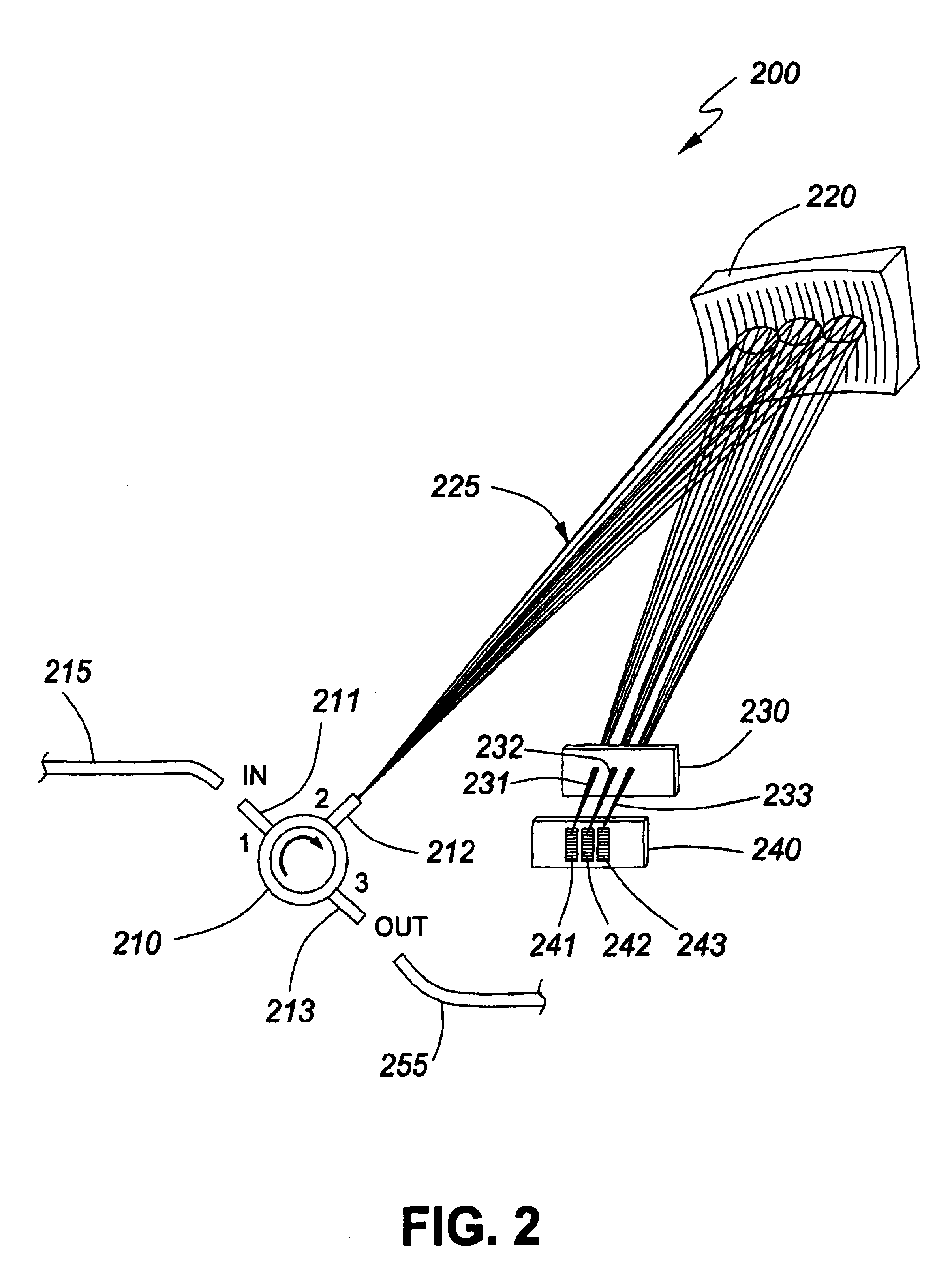
[0027]FIG. 2 illustrates one embodiment of an equalizer in accordance with the instant invention. The equalizer 200 includes an input optical fiber 215, an output optical fibre 255, a circulator 210, a concave diffraction grating 220, a waveplate...


PUM


Abstract

A method and apparatus is described for controlling the attenuation of multiple wavelengths signals propagating in an optical fiber, that may have a time-dependent power in each signal, to provide an output signal having a desired attenuated power in each of the multiple signals. An equalizer may be used that has various optical elements to focus and disperse light, such as a concave diffraction grating and a modulator array having modulators disposed on a concave surface. The equalizer may also be coupled to various components such as a circulator or thermally expanded core fibers.

Description

[0001]This application is a continuation-in-part of U.S. patent application Ser. No. 09 / 727,446 filed Dec. 4, 2000.FIELD OF THE INVENTION[0002]This invention relates to the field of optical communications and, in particular, to attenuation devices used in optical communication networks.BACKGROUND[0003]In multiplexed optical communication networks, a single optical fiber typically carries a signal having multiple independent data channels with each data channel assigned to a different wavelength. Such networks are referred to as wavelength division multiplexed (WDM) networks. In WDM networks, the signal at each of these different wavelengths may be routed to different destinations. However, if a signal has too much power, it may overload a receiver in the network. An attenuator may be used to reduce signal intensity that may otherwise overload a receiver in the network. An attenuator may also be used for other functions such as to block extraneous signals at other wavelengths and to ...

Claims


Application Information

Patent Timeline
IPC IPC(8): G02B6/34
CPCG02B6/29391G02B6/2931
Inventor MOROZOV, VALENTINE N.CHURIN, YEVGENIYSHEN, JINXI
Owner JDS UNIPHASE CORP
Why Eureka
Try Eureka