
Landmark-based location of users

Inactive Publication Date: 2005-05-24
MICROSOFT TECH LICENSING LLC
View PDF7 Cites 270 Cited by
  • Summary
  • Abstract
  • Description
  • Claims
  • Application Information

AI Technical Summary

Benefits of technology

[0009]The present invention is likewise directed to providing a user with an accessible and efficient database of landmarks and other visual cues from which the user's position can be determined.
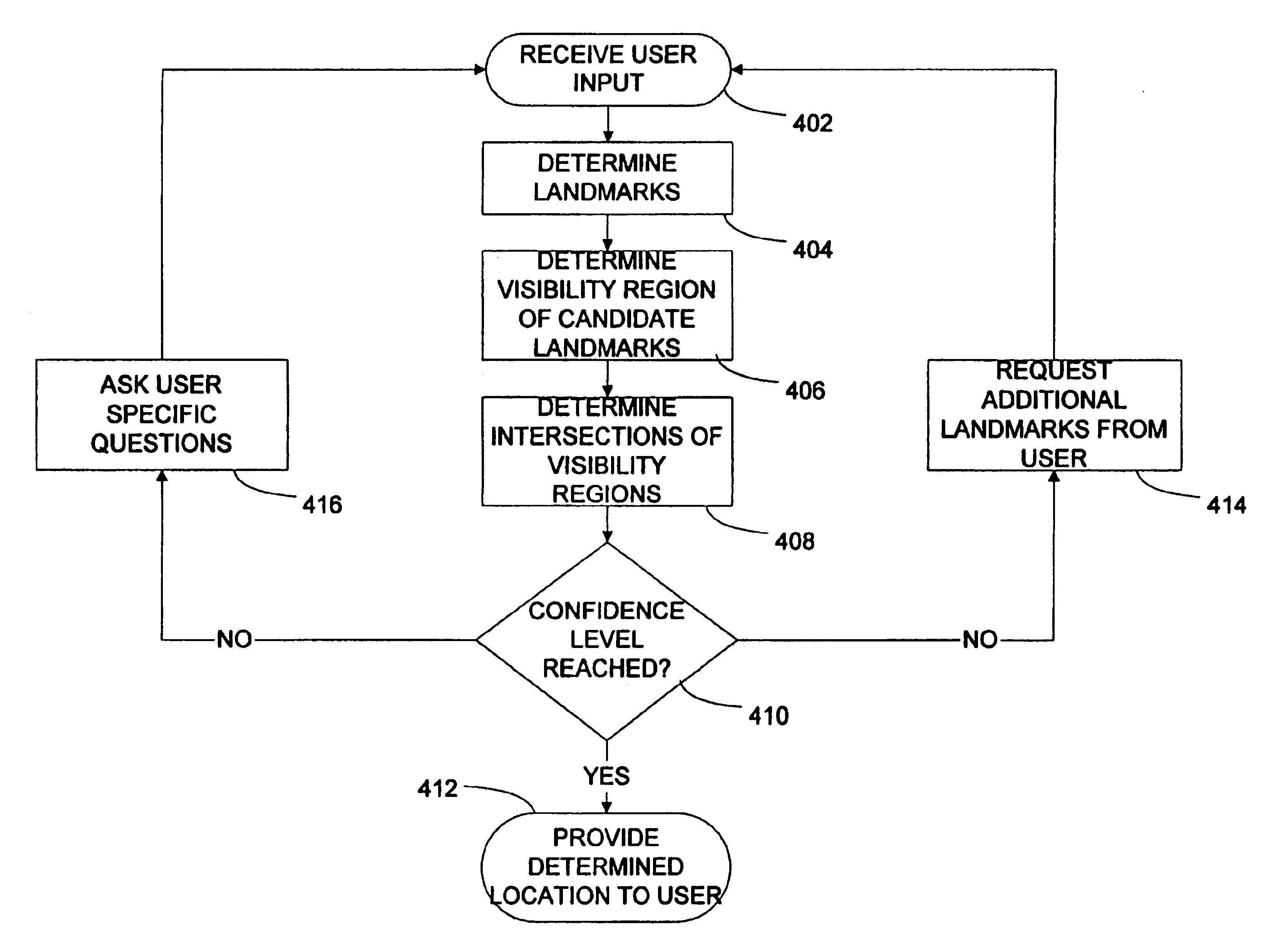
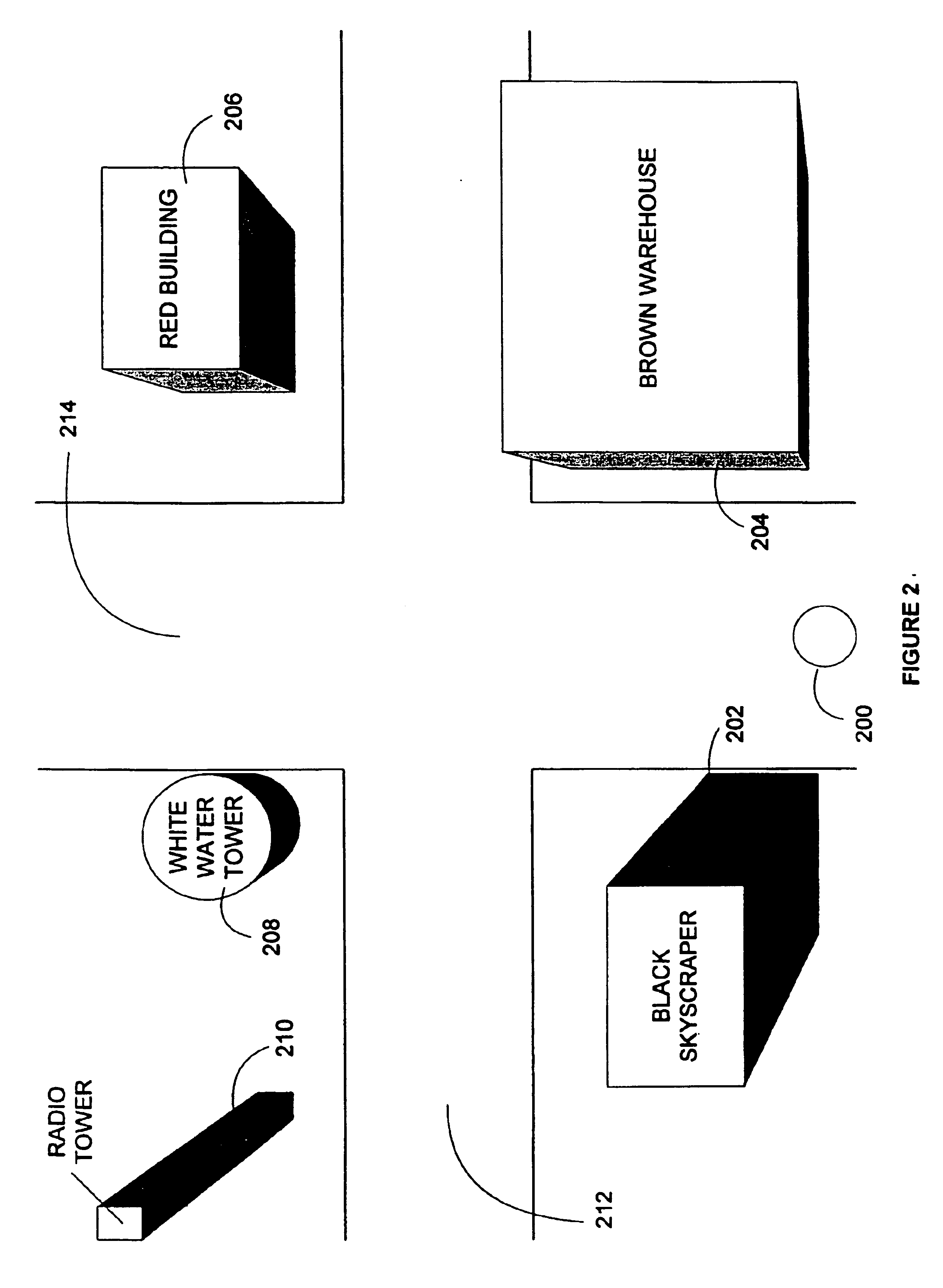
[0014]Once the portable computing device has been provided with the user's input, it can compare the user's descriptions of their surroundings to the database to identify the landmarks that the user is describing. Visibility regions, indicating those areas from which the landmark can be seen, can be calculated for each landmark identified, or for a more focused subset, such as those landmarks that have small visibility regions. If the intersection of the visibility regions yields only one location, then the system can return it as the user's location. Alternatively, if the intersection of the visibility regions yields an area, or multiple areas with differing probabilities of likelihood, the system can prompt the user for more information. The user's location can, therefore, be located by determining a location which uniquely matches the description provided by the user of their current surroundings.

Problems solved by technology

Current systems for locating a user rely on extensive, and expensive, infrastructure to support the system.
Both the GPS system and the E-911 system require the installation and maintenance of expensive and dedicated infrastructure.
These systems also suffer from other drawbacks inherent in their design.
For example, the GPS system does not work indoors or in locations, such as downtown areas, with significant obstructions to the signal paths between the user and the satellites and cellular telephone base stations.
Additional location determining systems can be used in confined areas, but they too suffer from the need to purchase and maintain dedicated infrastructure.
Such systems suffer from the same complex infrastructure problem as GPS or E-911.
Because of the amount of infrastructure needed for even small areas, such systems cannot be scaled well to larger areas, such as a whole town or metropolitan area.
Additionally, some of these systems, such as infrared based systems, can be impacted by environmental concerns, such as direct sunlight.
In addition to the above problems, some of the known systems for determining a user's location suffer from privacy concerns.
Furthermore, because all of these systems rely on a central architecture, they all leave the user vulnerable to system outages when the infrastructure required is not properly operated or maintained by the central authority.

Method used


Image

  • Landmark-based location of users
  • Landmark-based location of users
  • Landmark-based location of users

Examples


Embodiment Construction

[0021]The present invention contemplates the determination of the location of a user based on the user's description of their surroundings. A portable computing device can be used to accept user input and determine the user's location, or communicate with additional computing devices to determine the user's location. A database of landmarks, and other visual cues, can be accessed to identify the landmarks described by the user. The database can further be used to determine the user's location by identifying a unique location that matches the user provided description of the user's view.

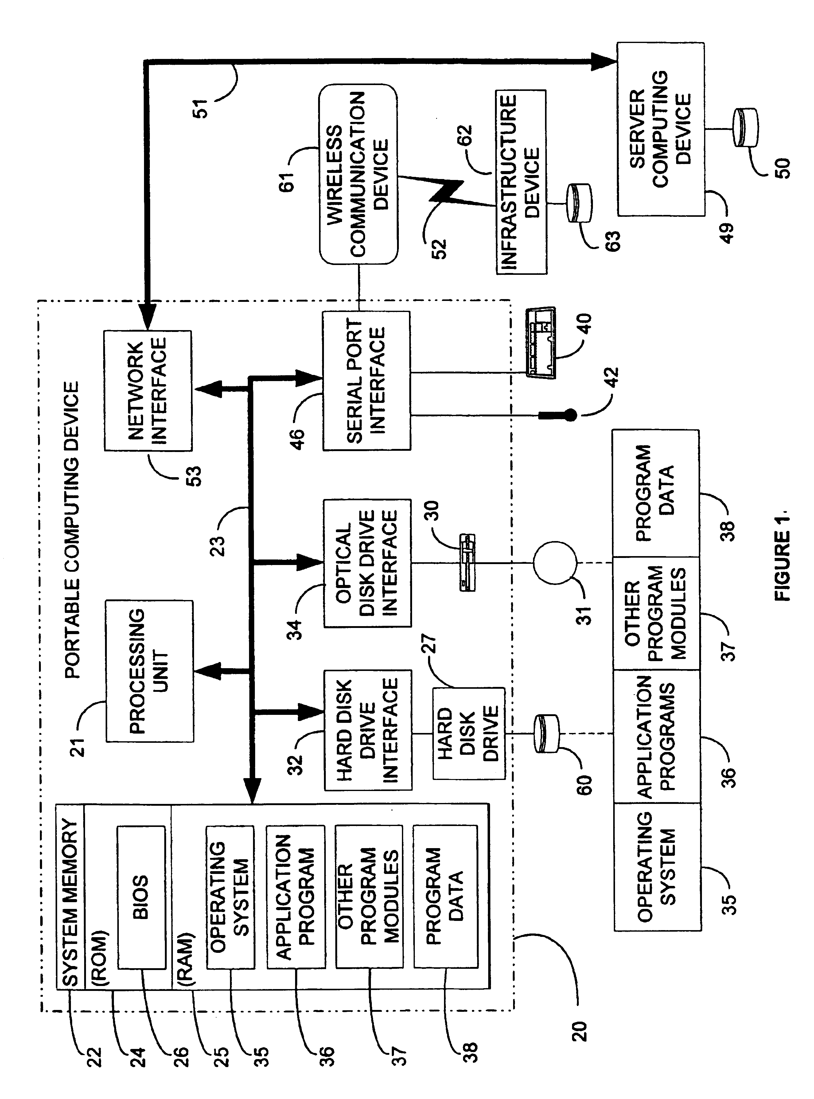
[0022]Turning to the drawings, wherein like reference numerals refer to like elements, the invention is described hereinafter in the context of a computing environment. Although it is not required for practicing the invention, the invention is described as it is implemented by computer-executable instructions, such as program modules, that are executed by a computing device. Generally, program modules...


PUM


Abstract

Humans identify location and directions based on visual cues, such as landmarks, rather than a precise coordinate grid. A database of landmarks can be used to determine the location of a user who can merely describe their location in the same manner they would to any human contact. The location of the user can be determined based on the landmarks described in the input, and the areas from which all of those landmarks are visible. Various databases can be used, including text-based and three-dimensional. Similarly, various mechanisms can be used to determine the user's location, including hierarchical approaches, query optimization approaches, and visibility percentage approaches. Ultimately, the user's location can be determined without the need for expensive, dedicated infrastructure, without compromising the user's security, and without subjecting the user to system outages.

Description

RELATED APPLICATION[0001]This application is related to and claims priority to U.S. patent application Ser. No. 10 / 097,285, entitled “LANDMARK-BASED LOCATION OF USERS,” filed Mar. 14, 2002, now U.S. Pat. No. 6,766,245 of which the present application is a continuation.TECHNICAL FIELD[0002]This invention relates generally to locating a mobile user and, more particularly, relates to locating a user through visual observations made by the user.BACKGROUND OF THE INVENTION[0003]An increasingly popular use of computing devices is to allow a user the ability to interact with their physical surroundings. For example, handheld computers can provide the user with information on topics of interest near the user, such as restaurants, copy centers, or automated teller machines. Similarly, laptop computers seek to allow a user to control devices located in close proximity to that laptop, such as a printer located in the same room. Additionally, specialized computing devices, such as navigational ...

Claims


Application Information

Patent Timeline
IPC IPC(8): G01C21/30G01C21/00G01C21/28H04Q7/20G01C21/20
CPCG01C21/20
Inventor PADMANABHAN, VENKATA N.
Owner MICROSOFT TECH LICENSING LLC
Learn More