Method for increasing physical layer flexibility in cable modem systems

Inactive Publication Date: 2005-05-24
JUMIPER NETWORKS INC
View PDF3 Cites 69 Cited by
  • Summary
  • Abstract
  • Description
  • Claims
  • Application Information

AI Technical Summary

Benefits of technology

[0045]In view of the above-described problems of the prior art, it is an object of the present invention to provide a method for increasing physical layer flexibility in cable modem systems. The present invention enables the CMTS to assign burst profiles and number of mini-slots to the CMs according to the CMs' robustness level. This is accomplished using the following method. First, the CMTS maintains the performance statistics of each CM. Next, when the CM performs a bandwidth request to the CMTS, the CMTS determines whether the CM is dynamic burst profile mode capable. If so, then the CMTS assigns a burst profile based on performance measurements on the CM and grants the CM a number of mini-slots per the burst profile parameters and the CM's request. Otherwise, if the CM is not dynamic burst profile mode capable, the CMTS assigns a burst profile per the current DOCSIS specification and assigns a number of min-slots per CM's request.

Problems solved by technology

The major limitation from the current standard is that only two burst profiles are used.
However, this is a sacrifice to the CMs which can successfully use 16-QAM and less Reed-Solomon parity, and this is a limitation to the system as a whole because the capacity of the upstream channel could be more efficiently utilized by some CMs by using a higher order of modulation or less Reed-Solomon parity.
However, there are other impairments that do not impact all CM signals received in the upstream, but may only impact a particular CM or CMs on a segment of the systems.
For example, impairments and distortion can be due to a tap or amplifier that is malfunctioning or has degraded.

Method used


Image

  • Method for increasing physical layer flexibility in cable modem systems
  • Method for increasing physical layer flexibility in cable modem systems
  • Method for increasing physical layer flexibility in cable modem systems

Examples


Embodiment Construction

[0052]The present invention will now be described in greater detail, which will serve to further the understanding of the preferred exemplary embodiments of the present invention. As described elsewhere herein, various refinements and substitutions of the various embodiments are possible based on the principles and teachings herein.

[0053]The preferred embodiments of the present invention will now be described with reference to FIG. 5, wherein like components, frequencies, data rates, etc. are designated by like reference numerals throughout the various figures. Further, specific details and parameters are provided herein and are intended to be explanatory rather than limiting.

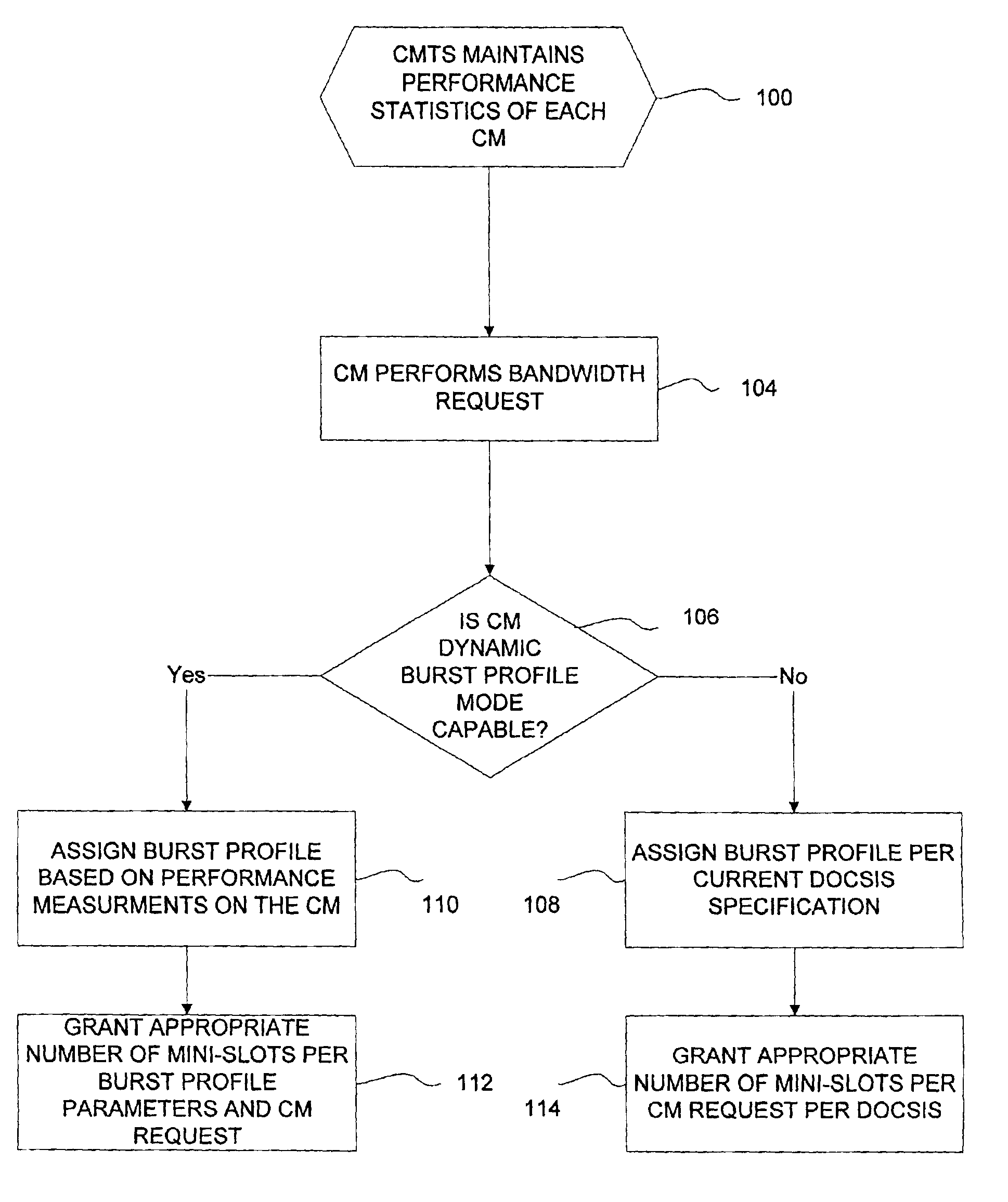
[0054]FIG. 5 illustrates a flow diagram of a method for increasing the physical layer flexibility in cable modem systems in accordance with the present invention. In step 100, the CMTS maintains the performance statistics of each CM. When the CM performs a bandwidth request to the CMTS in step 104, the CMTS det...


PUM


Abstract

In a cable modem system, signals are transmitted upstream from a cable modem (CM) to a cable modem termination unit (CMTS) when the subscriber desires to communicate with the headend. The invention described herein is directed to a method and apparatus for increasing the communication channel between the CM and the CMTS. This is accomplished by providing a method and apparatus for increasing physical layer flexibility in cable modem systems. In this manner, the CMTS is capable of assigning burst profiles and granting mini-slots to the CMs according to the CMs' burst profile and robustness level.

Description

FIELD OF THE INVENTION[0001]The present invention relates to cable modem systems. More particularly, the present invention is directed to a method and apparatus for increasing physical layer flexibility in cable modem systems.BACKGROUND OF THE INVENTION[0002]Recently, there has been an explosive growth for broadband services. As is well known in the industry, cable modem technology is one of the most popular methods of providing broadband services to subscribers. Cable modem currently competes with technologies such as Asymmetric Digital Subscriber Lines (ADSL). Many in the industry forecast that cable modem systems will be the prevailing technology for providing broadband services.[0003]FIG. 1 illustrates a simplified diagram of a conventional cable modem system. In the conventional cable modem system, a headend 2 is connected to multiple subscribers 12 (residence or business) via an access network 6 such as coaxial cable, Hybrid Fiber Coax (HFC), or wireless. The headend 2 is know...

Claims


Application Information

Patent Timeline
IPC IPC(8): H03M13/00H04L1/00H04L12/66
CPCH04L1/0003H04L12/66H04L1/0017H04L1/0009H04L1/0006H04L1/0057
Inventor HOU, VICTOR T.
Owner JUMIPER NETWORKS INC
Why Eureka
Try Eureka