Clamping device

a technology of clamping device and clamping head, which is applied in the direction of soldering device, manufacturing tool, auxillary welding device, etc., can solve the problems of high vibration frequency, cumbersome high-speed wire clamping, and inability to meet the needs of high-speed wire clamping, so as to simplify the assembly of the clamping device and reduce the number of components

Inactive Publication Date: 2005-05-31
ASM TECH SINGAPORE PTE LTD
View PDF4 Cites 9 Cited by
  • Summary
  • Abstract
  • Description
  • Claims
  • Application Information

AI Technical Summary

Benefits of technology

[0009]The present invention seeks to provide a design of a clamping device that serves

Problems solved by technology

Even so, the wire clamp needs to have high static and dynamic stiffness thus giving rise to high resonant frequencies of vibration.
This makes it cumbersome for present-day high speed wire clamping wherein the clamp may need to operate at a rate of about 20 times per second or even more.
At this speed of operation, the long term reliability of the clamp is also questi

Method used


Image

  • Clamping device
  • Clamping device
  • Clamping device

Examples


Embodiment Construction

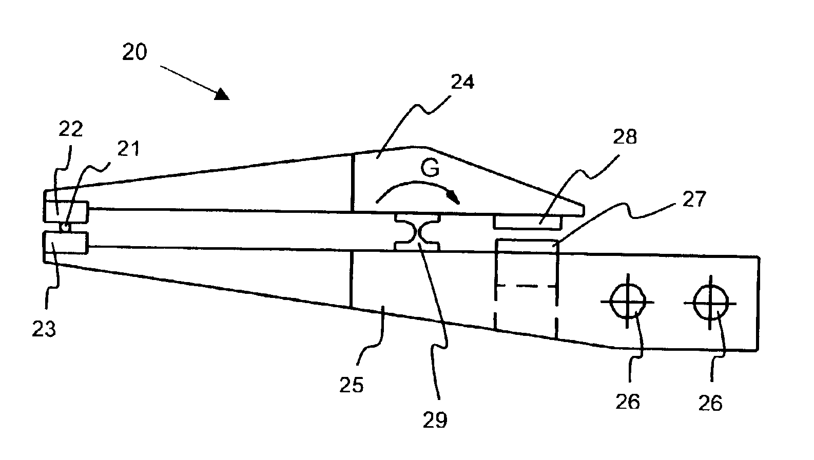
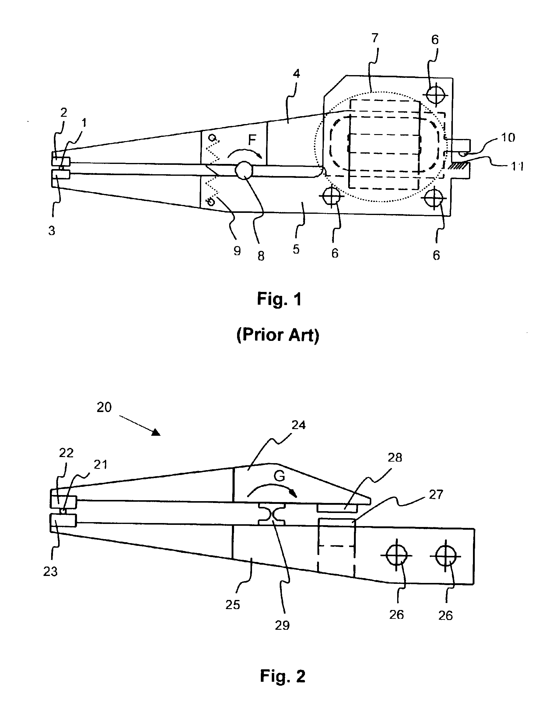
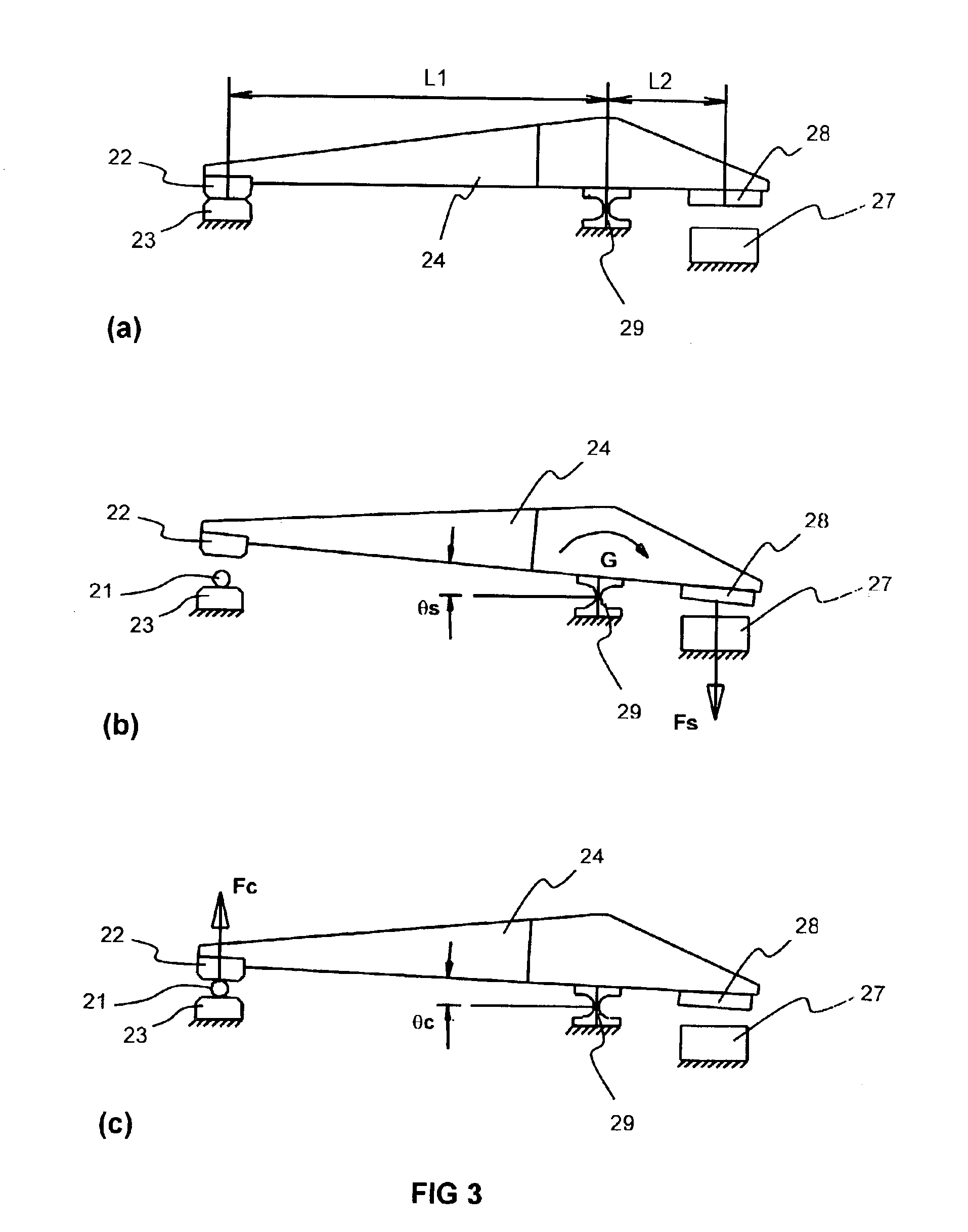
[0022]The structure and function of a clamping device according to the preferred embodiments of the present invention are now described. FIG. 2 shows a clamping device for clamping an object, in the form of a wire clamp 20 for clamping a bonding wire 21 according to a first preferred embodiment of the present invention. The wire clamp 20 includes a pair of clamping arms, one of which may be a fixed arm 25 mounted on a bonder body (not shown) using mounting holes 26. The other clamping arm may be a movable arm 24 that is arranged in a pivotal relationship with the fixed arm 25 about a pivot point. The movable arm 24 is mounted on the fixed arm 25 using a flexure bearing 29, which is designed to restrict all degrees of freedom of the movable arm 24 but one, with respect to the fixed arm 25. All three translational degrees of freedom and the two rotational degrees of freedom apart from that indicated by arrow G, of the movable arm 24, are substantially restricted. In other words, the f...


PUM

PropertyMeasurementUnit
Forceaaaaaaaaaa
Elasticityaaaaaaaaaa
Specific strengthaaaaaaaaaa

Abstract

A clamping device is provided for clamping an object, such as bonding wire for a wire bonding machine. The device comprises a pair of clamping arms arranged in pivotal relationship with each other about a pivot point, the clamping arms having clamping ends movable between an open position and a closed position. An attraction device is operative to provide an attraction force between the clamping arms about the pivot point. The device includes biasing means that is operative to provide a biasing force in opposition to the attraction force about the pivot point, such that the biasing force is operative to bias the clamping ends towards the closed position. In a preferred embodiment, the biasing means comprises a flexure bearing.

Description

FIELD OF THE INVENTION[0001]The present invention relates to a clamping device, especially but not limited to a clamping device in the form of a wire clamp used generally in wire bonding machines or wire bonders in the semiconductor assembly industry.BACKGROUND AND PRIOR ART[0002]In a wire bonding process, electrically conductive wires are bonded between electrical contact pads found on a semiconductor die and leads on a substrate onto which the die is attached, usually a semiconductor leadframe. The wire needs to be held firmly, fed to the bonding site and stripped off at appropriate junctures in the process. This is usually achieved using a wire clamp. Over the years, the operational speed of wire bonding machines has increased considerably, with the result that the wire clamp needs to be actuated at high speed while exerting controlled force on the wire being clamped, without damaging the wire.[0003]Modern day wire bonders for making so-called “ball-bonds” are designed to execute...

Claims


Application Information

Patent Timeline
IPC IPC(8): B25B5/00B23K20/00B25B5/06B25B5/04B23K37/04
CPCB23K20/004B23K37/0435B25B5/04B25B5/06H01L24/78H01L2224/786H01L2224/851H01L2924/00014H01L2924/01033H01L2924/01082H01L2924/01005H01L2924/01006H01L2224/48H01L2224/78621H01L2224/45099
Inventor GAUNEKAR, AJIT S.WIDDOWSON, GARY PETER
Owner ASM TECH SINGAPORE PTE LTD
Why Eureka
Try Eureka