Electronic camera having conductive elastic body provided for shield plate

a shield plate and elastic body technology, applied in the field of electronic cameras having conductive elastic bodies provided for shield plates, can solve the problems of increasing the level of electromagnetic noise generated at the ccd and/or its drive circuit, increasing raising the level of electromagnetic noise, so as to achieve the effect of preventing the leakage of electromagnetic noise generated at the circuit board for image-capturing element drives and achieving a higher degree of effectiveness

Inactive Publication Date: 2005-05-31
NIKON CORP
View PDF15 Cites 37 Cited by
  • Summary
  • Abstract
  • Description
  • Claims
  • Application Information

AI Technical Summary

Benefits of technology

[0010]An object of the present invention is to provide an electronic camera in which leak of electromagnetic noise generated at a circuit board for image-capturing element drive is prevented with a higher degree of effectiveness.

Problems solved by technology

As the clock rate achieves a higher frequency or as the level of the voltages read by the CCD rises, the level of electromagnetic noise generated at the CCD and / or its drive circuit increases.
However, in an electronic still camera mounted with a CCD having dimensions of 23.7 mm (height)×15.6 mm (width) with the number of its pixels exceeding 2,500,000, the level of electromagnetic noise leaking from the camera body cannot always be reduced to a specific level or lower simply by providing a shield plate between the CCD drive circuit board and the camera body, as in the prior art.
This, combined with a higher frequency of the read clock achieved to support a large number of pixels, raises the level of the electromagnetic noise.

Method used


Image

  • Electronic camera having conductive elastic body provided for shield plate
  • Electronic camera having conductive elastic body provided for shield plate
  • Electronic camera having conductive elastic body provided for shield plate

Examples


first embodiment

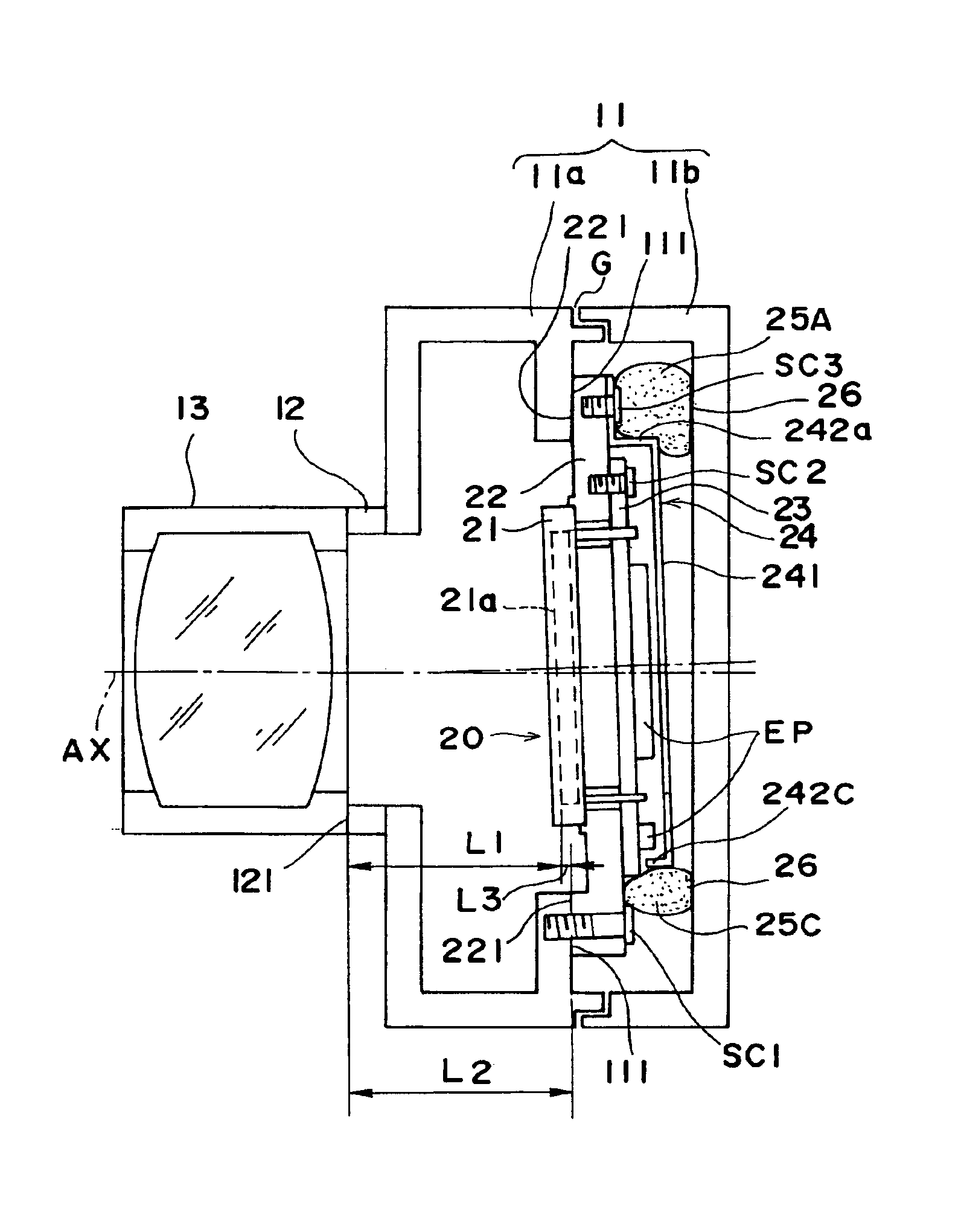
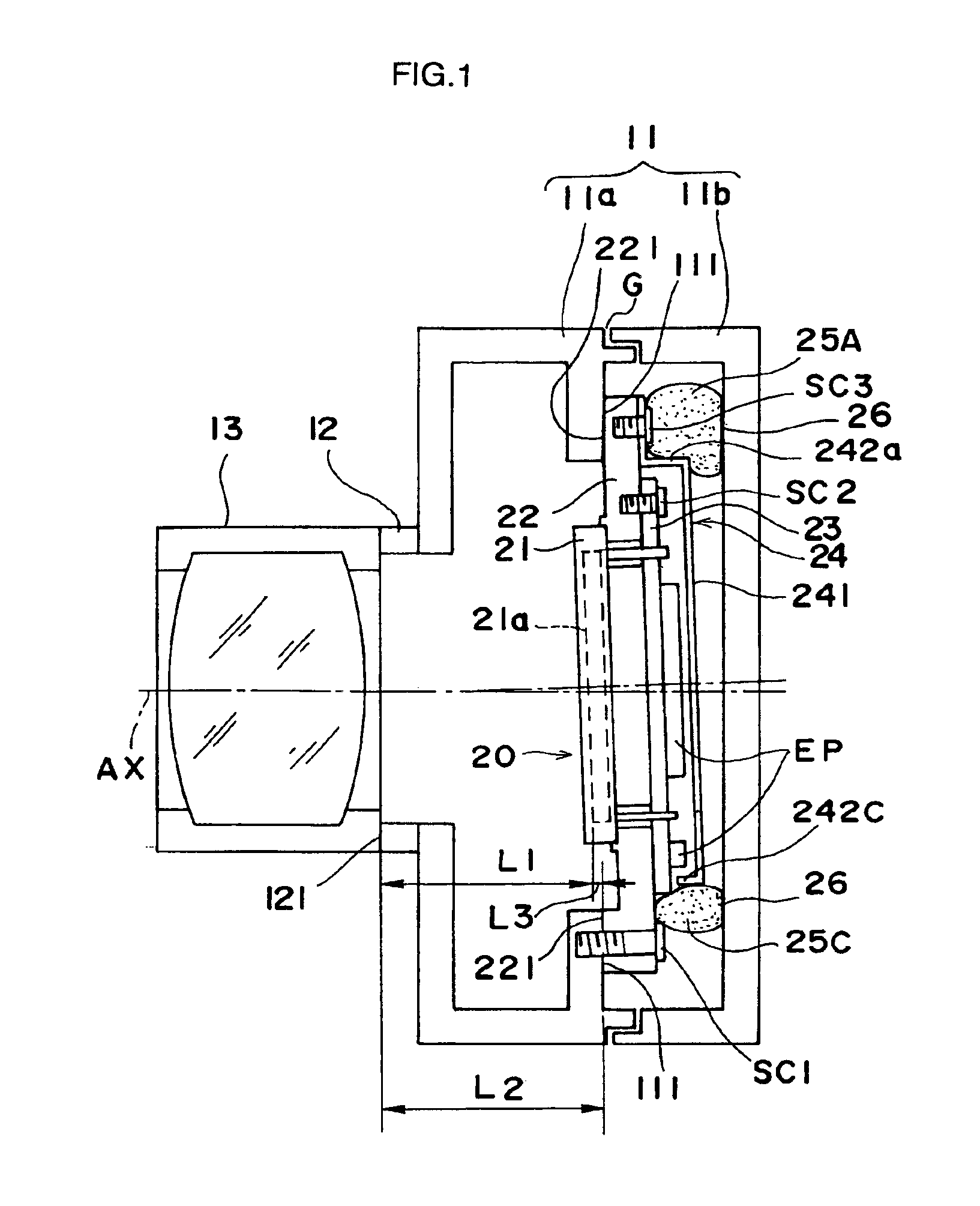
[0022]FIG. 1 is a longitudinal vertical cross sectional view illustrating a schematic structure of the electronic camera according to the present invention constituted as a lens-exchange type electronic still camera and FIG. 3 shows the inside of the camera as viewed from the rear with the rear body being removed. As illustrated in FIG. 1, a camera body 11 is constituted of a front body 11a and a rear body 11b formed from a conductive metal material, and a slight gap G is formed between the front body 11a and the rear body 11b. According to the present invention, the electromagnetic wave noise leaking through this gap G is effectively minimized.

[0023]A lens mount 12 is provided at the camera front body 11a, with an exchangeable taking lens 13 mounted on the lens mount 12. Subject light having passed through the taking lens 13 enters an image-capturing device 20. The image-capturing device 20 comprises a solid image-capturing element 21 such as a CCD having dimensions of 23.7 mm (hei...

second embodiment

[0035]The second embodiment of the electronic camera according to the present invention is now explained in reference to FIGS. 4-6. In the first embodiment described above, the bent portions 242a-242d are provided at the four sides of the shield plate 24 to prevent the electromagnetic wave noise from leaking through the gap between the shield plate 24 and a circuit board 23 at the periphery of the four sides of the shield plate 24. As illustrated in FIGS. 4 and 5, the second embodiment requires a flexible print board 32 or a lead wire 33 to be arranged between a socket ST1 provided at a side of a circuit board 123 toward the bottom of the camera and a socket ST2 provided at a circuit board 31 located in the lower portion of the camera. For this reason, there is no bent portion at the lower side of the shield plate 124. As a result, there is a concern that electromagnetic wave noise may leak through the gap between the lower side of the shield plate 124 and the circuit board 123.

[003...


PUM


Abstract

An image-capturing element that receives subject image light entering into a camera body through a taking lens is packaged and mounted within the camera body via a holder. The image-capturing element is mounted at the camera body by ensuring that its light-receiving surface is aligned with the image-forming position of the taking lens. A shield plate is provided on the rear side of the image-capturing element and a conductive elastic body is clamped and pressed between the shield plate and the rear portion of the camera body. The shield plate is grounded to the camera body having a large grounding capacity by the conductive elastic body. The conductive elastic body covers a gap at the periphery of the shield plate to absorb and block the electromagnetic wave noise which would otherwise leak through the gap.

Description

INCORPORATION BY REFERENCE[0001]The disclosures of the following applications are herein incorporated by reference:[0002]Japanese Patent Application No. 10-67019 filed Mar. 17, 1998[0003]Japanese Patent Application No. 11-229816 filed Aug. 16, 1999BACKGROUND OF THE INVENTION[0004]1. Field of the Invention[0005]The present invention relates to a technology that may be adopted to prevent electromagnetic noise leak in an electronic camera having an image-capturing element that receives subject image light entering into the camera body via a taking lens and is mounted in the camera body via a holder that holds the image-capturing element.[0006]2. Description of the Related Art[0007]In recent years, mega-pixel electronic still cameras provided with an image-capturing element (hereafter referred to as a CCD) with more than a million pixels have been put into practical use. A CCD reads out voltages stored at the individual pixels in units of single lines in response to a read signal having...

Claims


Application Information

Patent Timeline
Patent Type & Authority Patents(United States)
IPC IPC(8): G03B17/02H04N5/225
CPCH04N5/2253H04N23/54
Inventor UCHIYAMA, TAKAYUKI
Owner NIKON CORP
Why Eureka
Try Eureka