Sensor panel for detecting pen signal transmitted by pen

Active Publication Date: 2020-07-30
WACOM CO LTD
View PDF0 Cites 1 Cited by
  • Summary
  • Abstract
  • Description
  • Claims
  • Application Information

AI Technical Summary

Benefits of technology

The present patent provides a method to block electromagnetic noise in a sensor panel without impacting the removal of common mode noise by a differential method. The method involves using a first guard trace that extends and is disposed within a region where a component other than the guard trace is expected to block the electromagnetic noise. The first guard trace is also close to the first trace in a region where no component other than the guard trace is expected to block the electromagnetic noise. This ensures that the electromagnetic noise from outside is sufficient blocked without unduly impacting the removal of common mode noise.

Problems solved by technology

However, according to the findings of the study conducted by the inventor of the present application, the configuration of the outermost shielding trace disclosed in Patent Document 1 does not sufficiently block electromagnetic noise entering from outside.
This may be because the routing traces and the outermost shielding trace are too far apart.
However, the inventor has found that this configuration raises another issue when the above-described differential method is used.
However, extending the guard trace along the routing traces results in an increase in the capacitance between the guard trace and a routing trace disposed at an outermost position among the plurality of routing traces extending side by side.
This raises the possibility that common mode noise may not be sufficiently removed by the differential method.

Method used


Image

  • Sensor panel for detecting pen signal transmitted by pen
  • Sensor panel for detecting pen signal transmitted by pen
  • Sensor panel for detecting pen signal transmitted by pen

Examples


Embodiment Construction

[0018]Hereinafter, an embodiment of the present disclosure will be described in detail with reference to the accompanying drawings.

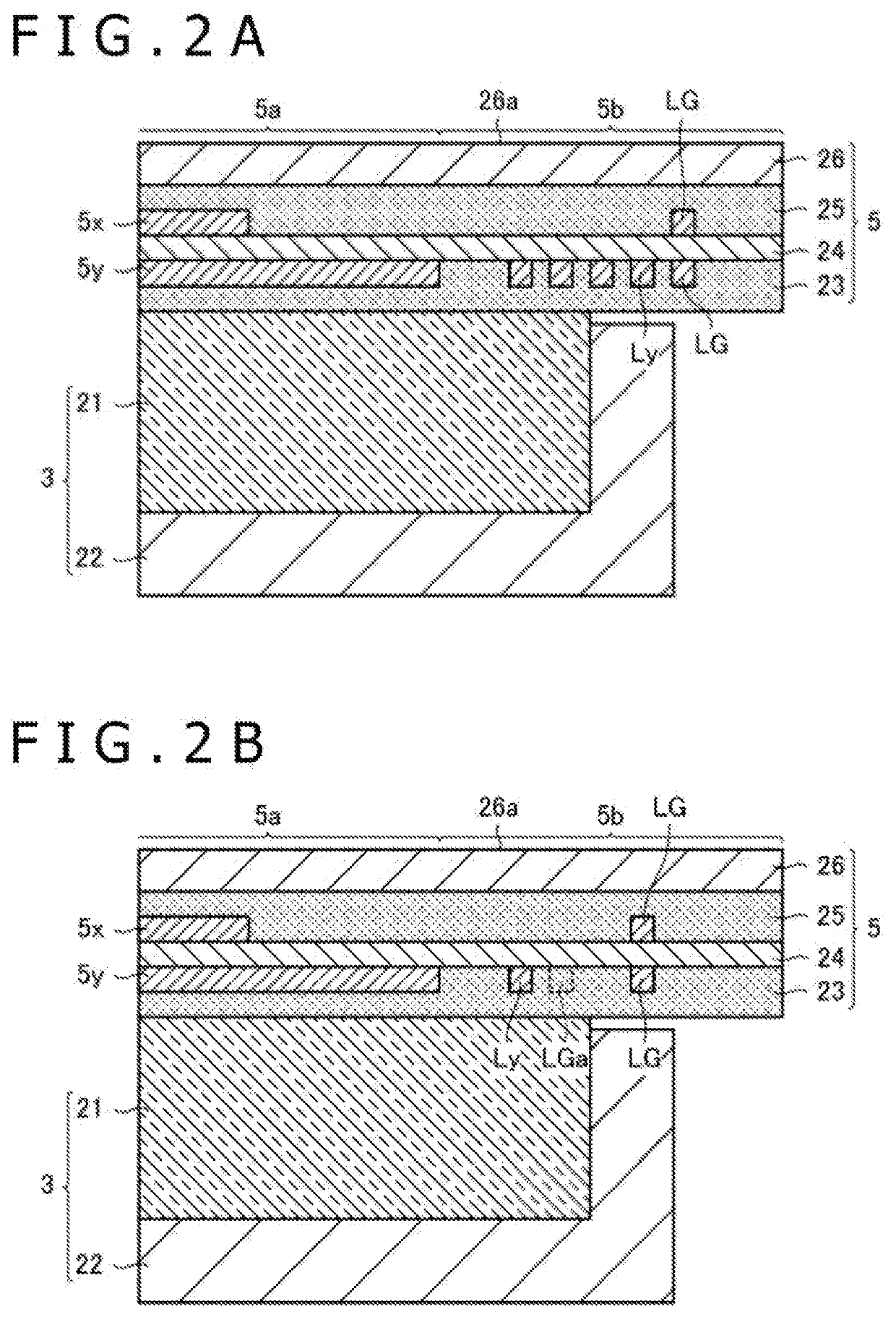
[0019]FIG. 1 is a diagram illustrating configurations of an electronic apparatus 1 and an active pen 10 according to the first embodiment of the present disclosure. FIG. 2A is a cross-sectional view of the electronic apparatus 1 taken along line A-A illustrated in FIG. 1. FIG. 2B is a cross-sectional view of the electronic apparatus 1 taken along line B-B illustrated in FIG. 1.

[0020]The electronic apparatus 1 according to the present embodiment is, for example, a tablet computer, and includes a host controller 2, a display panel 3, a sensor controller 4, and a sensor panel 5, as illustrated in FIG. 1.

[0021]The host controller 2 is a computer including a processor and a memory (both not illustrated). The processor reads and executes a program stored in the memory to perform various types of processing such as control of each section of the electronic appa...


PUM


Abstract

A sensor panel includes: a plurality of first linear electrodes disposed in a detection region; a plurality of first routing traces; a plurality of first terminals disposed along one edge of the sensor panel parallel to a second direction; and a first guard trace extending and disposed on one side of the plurality of first routing traces farther away from the detection region. A first trace is one of the plurality of first routing traces connected to a first electrode that is a first linear electrode disposed farthest away from the plurality of first terminals among the plurality of first linear electrodes. A separation distance between the first trace and the first guard trace is not constant in the second direction in a first region adjacent to the detection region in the second direction. In the first region, the first guard trace has a portion intersecting a first direction.

Description

BACKGROUNDTechnical Field[0001]The present disclosure relates to a sensor panel for detecting a pen signal transmitted from a pen, and more particularly, to a sensor panel including guard traces for absorbing electromagnetic noise entering from outside.Description of the Related Art[0002]In a tablet electronic apparatus having a function of detecting the position of a finger or a stylus, a sensor panel is disposed on a display panel. The sensor panel includes a plurality of linear electrodes including a plurality of X electrodes and a plurality of Y electrodes. The plurality of X electrodes extend in a Y direction and are disposed at equal intervals in an X direction. The plurality of Y electrodes extend in the X direction and are disposed at equal intervals in the Y direction. The display panel includes a bezel region in which a plurality of flexible printed circuit (FPC) connection terminals and routing traces are provided for corresponding ones of the plurality of linear electrod...

Claims


Application Information

Patent Timeline
IPC IPC(8): G06F3/044G06F3/0354
CPCG06F3/03545G06F3/0442G06F3/0412G06F3/0418G06F3/044G06F2203/04107G06F2203/04111G06F3/0446
Inventor KADOWAKI, JUN
Owner WACOM CO LTD
Why Eureka
Try Eureka