Methods and apparatus for computed tomography imaging
- Summary
- Abstract
- Description
- Claims
- Application Information
AI Technical Summary
Benefits of technology
Problems solved by technology
Method used
Image
Examples
Embodiment Construction
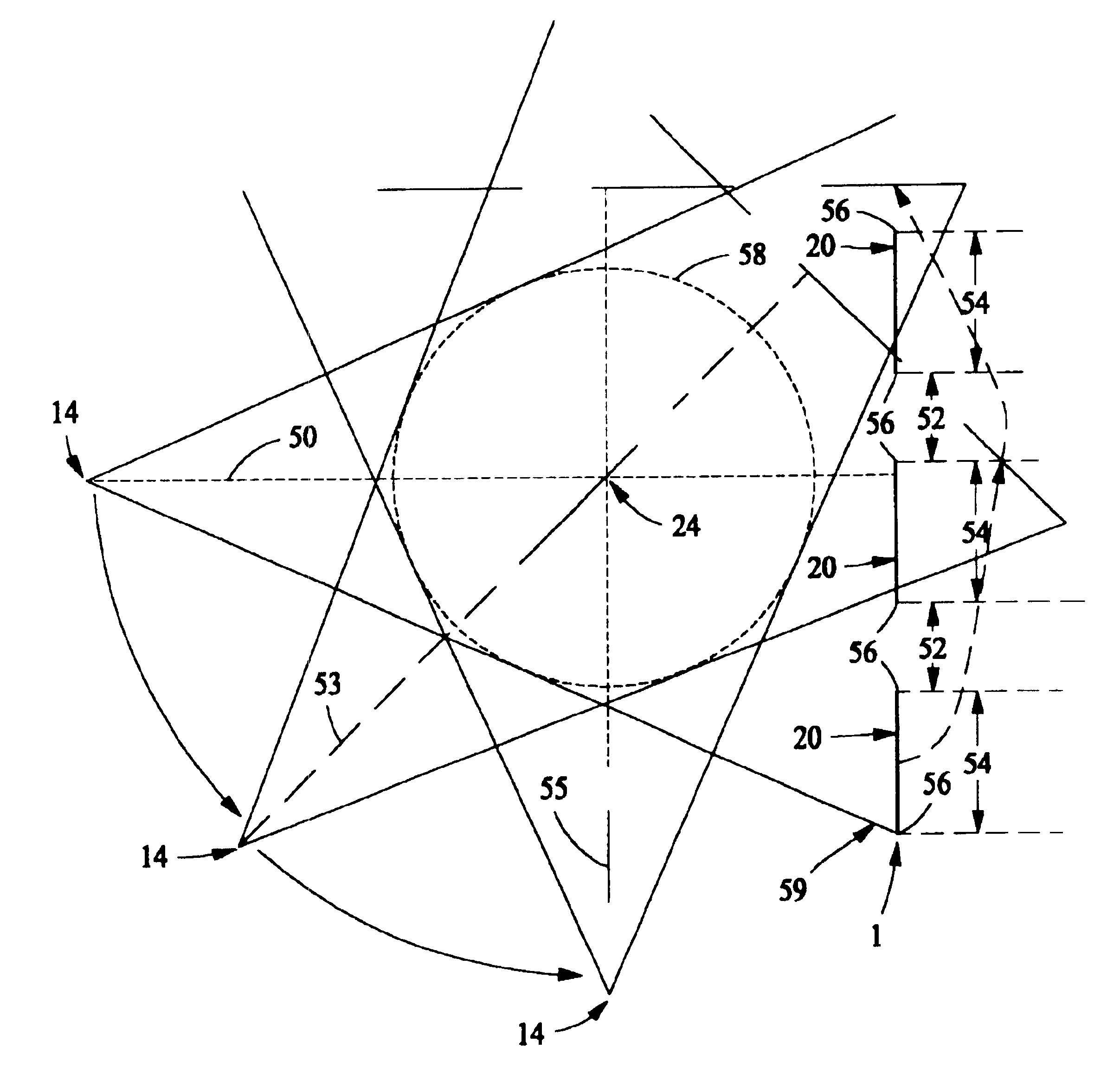
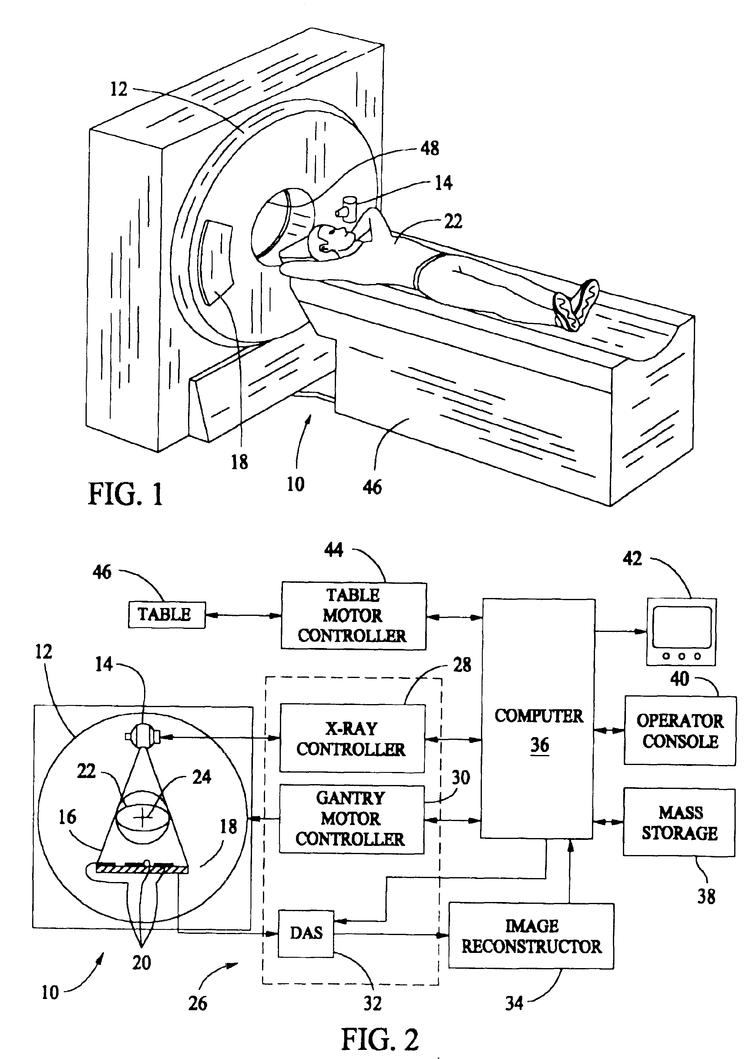
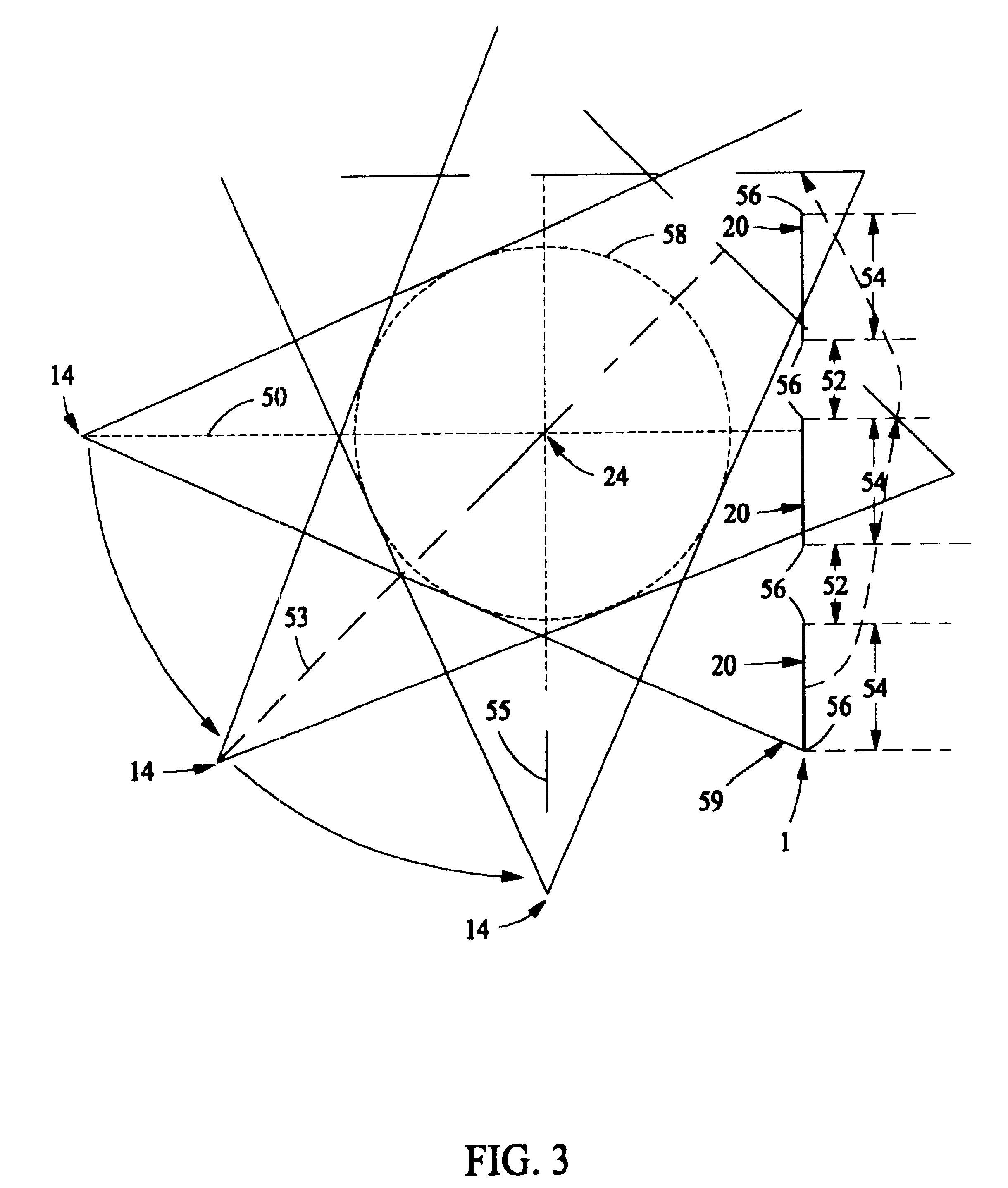
[0017]Referring to FIGS. 1 and 2, a computed tomography (CT) imaging system 10 is shown as including a gantry 12 representative of a “third generation” CT scanner. Gantry 12 has an x-ray source 14 that projects a beam of x-rays 16 (shown in FIG. 2) toward a detector array 18 on the opposite side of gantry 12. The relative orientation of the x-ray source 14 and detector array 18 remains fixed. Referring to FIG. 2, detector array 18 is formed by detector sections 20, which together sense the projected x-rays that pass through an object (ignoring the scatter component of the x-ray intensity), such as a medical patient 22. Each detector section 20 includes a plurality of detector elements (not shown) that each produces an electrical signal that represents the intensity of an impinging x-ray beam on the detector elements. This data can be used to estimate the attenuation of the beam as it passes through patient 22 facilitating generation of the line integrals of the linear attenuation co...
PUM
 Abstract
Description
Claims
Application Information
 - R&D
- Intellectual Property
- Life Sciences
- Materials
- Tech Scout
- Unparalleled Data Quality
- Higher Quality Content
- 60% Fewer Hallucinations
Browse by: Latest US Patents, China's latest patents, Technical Efficacy Thesaurus, Application Domain, Technology Topic, Popular Technical Reports.
© 2025 PatSnap. All rights reserved.Legal|Privacy policy|Modern Slavery Act Transparency Statement|Sitemap|About US| Contact US: help@patsnap.com


