Tilt focus method and mechanism for an optical drive

a technology of optical drives and tilting focus, which is applied in the direction of instruments, disposition/mounting of heads, and maintaining head carrier alignment, etc., can solve the problems of linear actuators with relatively high friction devices, affecting performance parameters such as access time, data transfer rate, and requiring precise track alignmen

Inactive Publication Date: 2005-05-31
DPHI ACQUISITIONS
View PDF15 Cites 7 Cited by
  • Summary
  • Abstract
  • Description
  • Claims
  • Application Information

AI Technical Summary

Benefits of technology

[0014]By dynamically adapting the position of the objective lens during operation of the drive, the system can respond to variations in the relative position of the data layer caused by imperfections in the manufacture of the disk, manufacture and assembly tolerances of co...

Problems solved by technology

While linear actuators have proved useful in a number of contexts, such as for reading/writing CDs and DVDs, the location and mass of the components in linear actuators has typically affected performance parameters such as access time, data transfer rates, and the like.
In addition, linear actuators are relatively high-friction devices and require precise track alignment.
Linear actuators typically add substantial thickness to a read/write or drive device and generally do not scale well toward miniaturization.
Also, linear actuators are typically unbalanced systems in that the mass of the components, including the objective tens, is not evenly distributed relative to any pivot point.
As a result, such actuators are highly susceptible to shock and vibration.
However, relative movement between optical components, while perhaps useful for accommodating relatively large or massive components, presents certain disadvantages, including a relatively large form factor and the engineering and manufacturing associated with establishing and maintaining optical alignment between moveable components.
Such alignment often involves manual and/or individual alignment or adjustment procedures which can undesirably increase manufacturing or fabrication costs for a reader/writer, as well as contributing to costs of design, maintenance, repair and the like.
Ideally, the conical beam is perpendicular to the surface of the disk, although, given irregularities in the manufacture of the disk and its component layers (i.e. disk flatness), bearing defect frequencies, and tolerances in the manufacture and assembly of the mechanical components, as well as shock and vibrations imparted into the disk drive during operation, perpendicularity between the disk surface and light beam is difficult to maintain.
However, such a focus mechanism, including the optical elements thereof, tends to be large in size and, ...

Method used


Image

  • Tilt focus method and mechanism for an optical drive
  • Tilt focus method and mechanism for an optical drive
  • Tilt focus method and mechanism for an optical drive

Examples


first embodiment

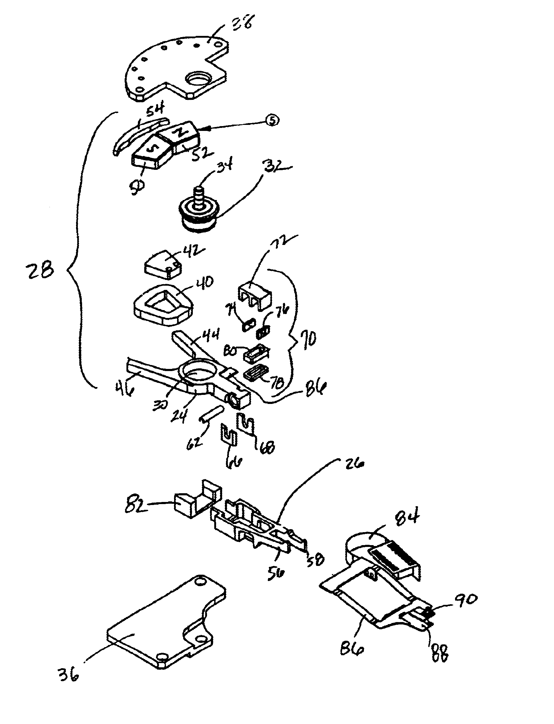
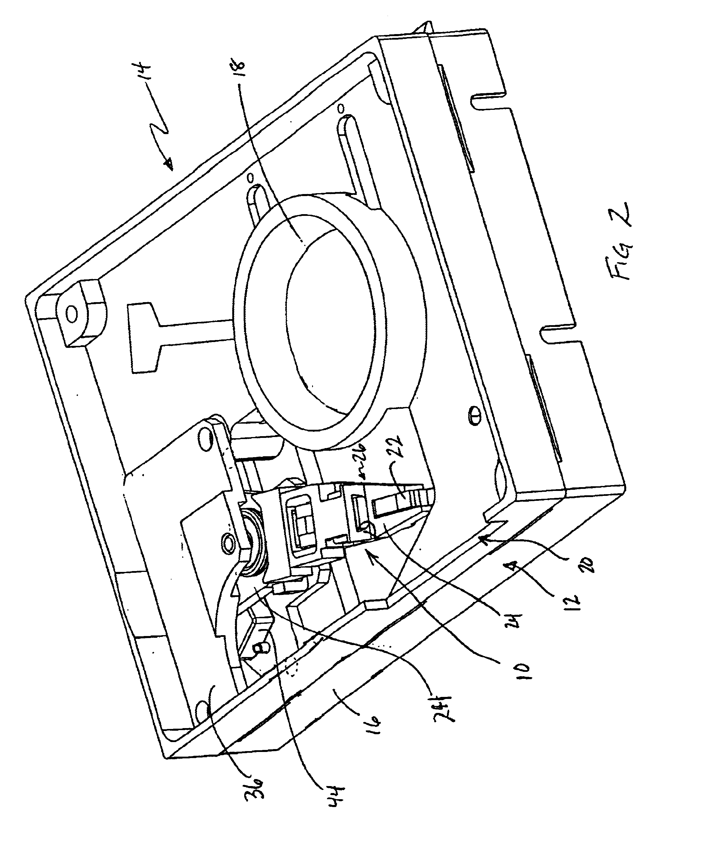
[0051]Turning to FIG. 2, the tilt focus mechanism 10 is shown within the housing 12 of an optical drive 14. The housing 12 includes a base plate 16 having an aperture 18 for receiving a spin motor (not shown) and a slot 20 to receive a diskette containing an optical disk (not shown). The cover plate has been removed. A diskette is inserted into the slot 20 and engages the spin motor positioned in aperture 18. An optical pick up unit 22 is positioned at the distal end of the tilt focus mechanism 10 and directs a light beam (not shown), such as a laser, to the optical disk which is spinning at a rapid rate. The light beam may be used to write information to the disk or may be used to read information resident on the disk. Because information is stored on the disk in tracks, typically concentrically arranged, the optical pick up unit (OPU) 22 must be able to traverse the surface of the disk from the inside to the outside diameter in order to access the information formatted on the disk...

third embodiment

[0059]the present invention is shown in FIGS. 16-22. In general, this embodiment includes a tracking arm 100 for course movement in the X-Y direction (parallel to the surface of the optical disk) and a focus arm 102 for fine tracking and for focus movement in the Z direction (perpendicular to the disk surface). Thus, unlike the tracking arm 24 in the first two embodiments, tracking is accomplished by two stages rather than one. Like the tracking arm 24 in the first two embodiments, the tracking arm 100 includes a bearing mount bore 104 for receiving a bearing cartridge 106 which allows the tracking arm 100 to pivot about a shaft 108 mounted between a tracking VCM return plate and a VCM magnet plate (not shown) of the optical drive. As should be appreciated by one skilled in the art, as an alternative, the shaft 108, in this embodiment or in any of the disclosed embodiments, may be fixed or stationary. A coil 110, wound around bobbin 112, is mounted between a pair of support members ...

fourth embodiment

[0064]A fourth embodiment is disclosed in FIGS. 23-29. In general, this embodiment comprises a single actuator arm 200 having a bearing bore mount 202 which mounts to a bearing cartridge 204. The bearing cartridge 204 is rotatably connected to a shaft 206 mounted between a tracking VCM return plate 208 and the cover or a similar cap structure (not shown). For coarse and fine tracking purposes, the actuator arm 200 moves in a conventional manner responsive to torque induced by VCM 210. The VCM 210 comprises a coil 212 wound around a bobbin 214 placed within a pair of arms 216 and 218 at the rear end of the actuator arm 200. Permanent magnets220 and 222, in cooperation with alternating current flowing in the coil 212 and the return path provided by tracking VCM return plate 208 and tracking VCM magnet plate 224, create the necessary torque to pivot the actuator 200 about the shaft 206. The tracking VCM magnet plate 224 further includes an aperture 226 to provide clearance for the shaf...


PUM


Abstract

The present invention relates to a method and apparatus for dynamically positioning the objective lens in an optical disk drive to maintain focus despite loss of perpendicularity between the light beam and the information layer of the optical disk. Loss of perpendicularity may occur as a result of any number of factors, including irregularities in the manufacture of the disk, manufacturing tolerances and assembly of the disk drive components, bearing defect frequencies, shock and vibration. Failure to maintain perpendicularity may interference with the ability of the optical pick up unit of the drive to accurately read and write. The tilt focus mechanism of the present invention utilizes a rotary actuator that positions the objective lens in three dimensions relative to the surface of the optical disk. In one embodiment, a first voice coil motor positions the actuator generally in two dimensions parallel to the surface of the disk and a second voice coil motor positions the objective lens generally along an arcuate path orthogonal to the surface of the disk.

Description

CROSS-REFERENCE TO RELATED APPLICATIONS[0001]The present application is related to U.S. patent application Ser. No. 09 / 315,398, filed May 20, 1999, entitled “Removable Optical Storage Device and System,” U.S. Provisional Application Ser. No. 60 / 140,633, filed Jun. 23, 1999, entitled “Combination Mastered and Writeable Medium and Use In Electronic Book Internet Appliance,” U.S. patent application Ser. No. 09 / 393,899, filed Sep. 10, 1999, entitled “Content Distribution Method and Apparatus,” U.S. patent application Ser. No. 09 / 393,150, filed Sep. 10, 1999, entitled “Writeable Medium Access Control Using a Medium Writeable Area,” U.S. patent application Ser. No. 09 / 548,128, filed Apr. 12, 2000, entitled “Low Profile and Medium Protecting Cartridge Assembly,” U.S. patent application Ser. No. 09 / 560,781, filed Apr. 28, 2000, entitled “Miniature Optical Disk for Data Storage,” and U.S. patent application Ser. No. 09 / 540,657, filed Mar. 31, 2000, entitled “Low Profile Optical Head,” all of...

Claims


Application Information

Patent Timeline
IPC IPC(8): G11B7/09G11B5/596G11B7/085G11B7/095
CPCG11B5/59677G11B7/08576G11B7/0956G11B7/0925G11B7/0946
Inventor FREEMAN, ROBERT DAVIDBERG, THOMAS EDWARDNISS, DAVID WILLIAMRAYMOND, PETER JEFFREY
Owner DPHI ACQUISITIONS
Why Eureka
Try Eureka