Eureka AIR delivers breakthrough ideas for toughest innovation challenges, trusted by R&D personnel around the world.

Zoom lens and imaging device

a zoom lens and imaging device technology, applied in the field of zoom lenses and imaging devices, can solve the problems of difficult to obtain a high optical performance over the entire variable power range, the residual secondary spectrum of longitudinal chromatic aberration abruptly increases, and the image quality of color images is extremely degraded, etc., to achieve the effect of small residual secondary spectrum of longitudinal chromatic aberration, small size and high variable power ratio

Active Publication Date: 2008-10-02
FUJI PHOTO OPTICAL CO LTD
View PDF2 Cites 17 Cited by
  • Summary
  • Abstract
  • Description
  • Claims
  • Application Information

AI Technical Summary

Benefits of technology

[0013]In view of the above circumstances, it is an object of the invention to provide a zoom lens which has a small size, a high variable power ratio, and a small residual secondary spectrum of longitudinal chromatic aberration, and retains a high optical performance, and an imaging device with the zoom lens.
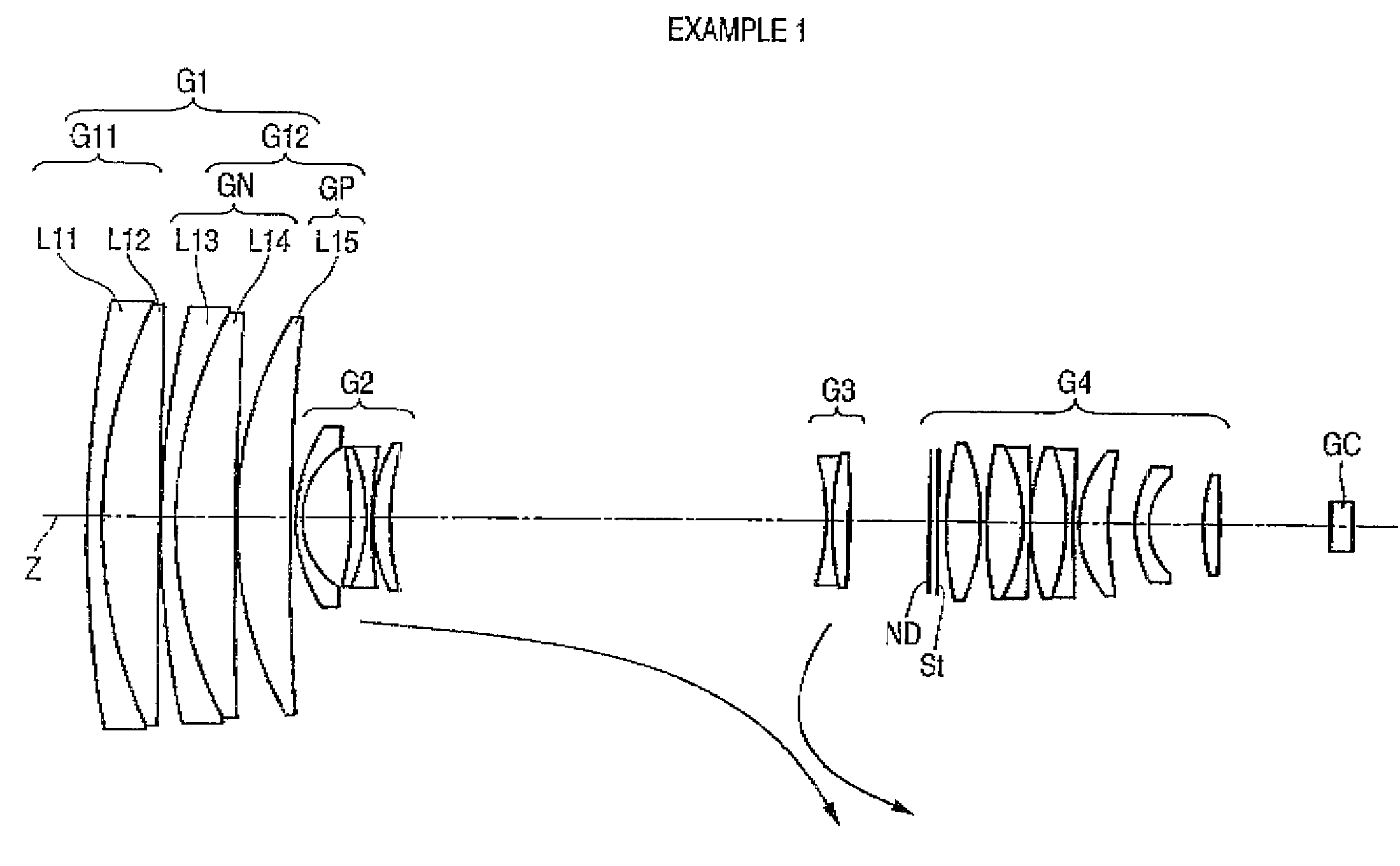
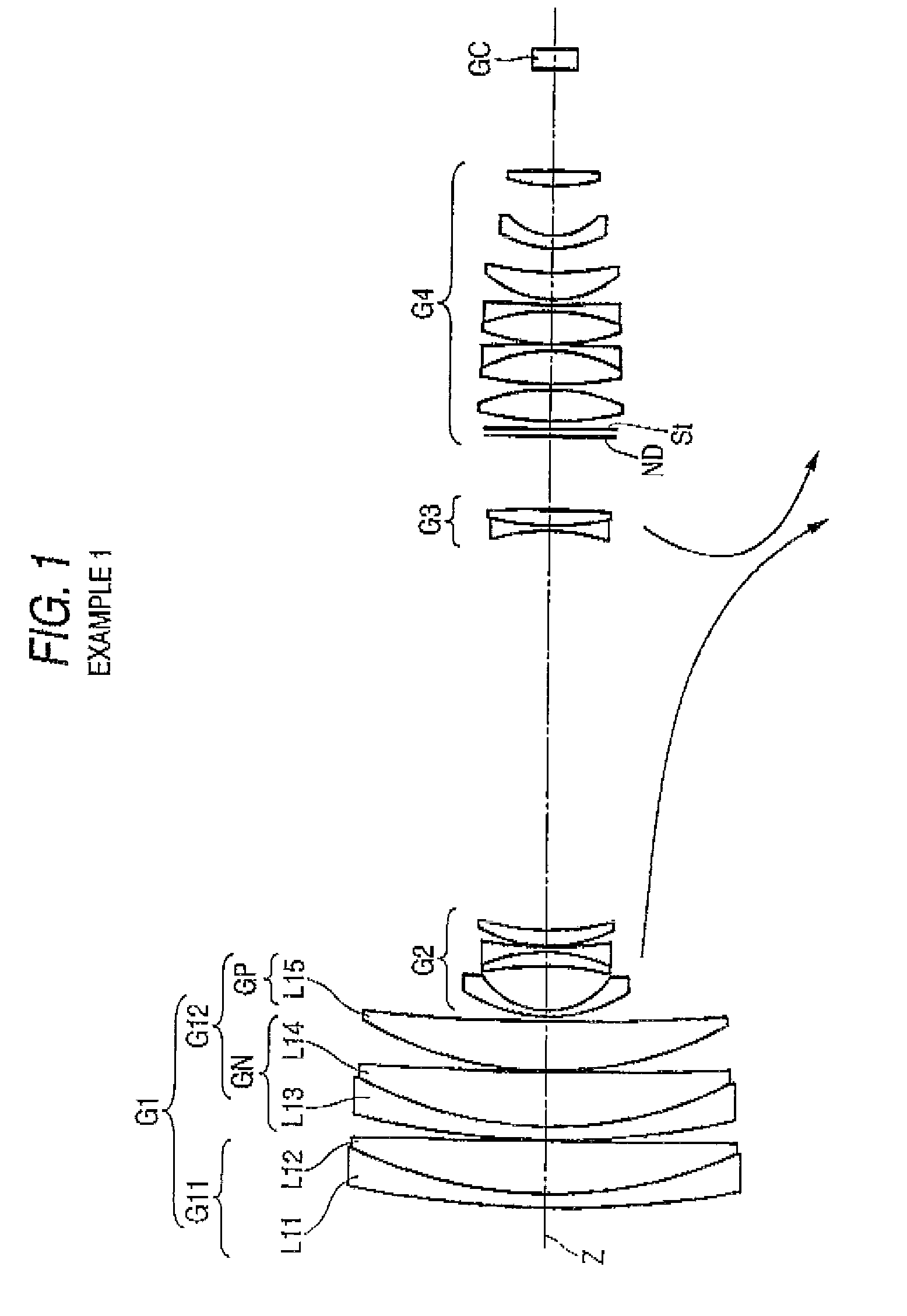
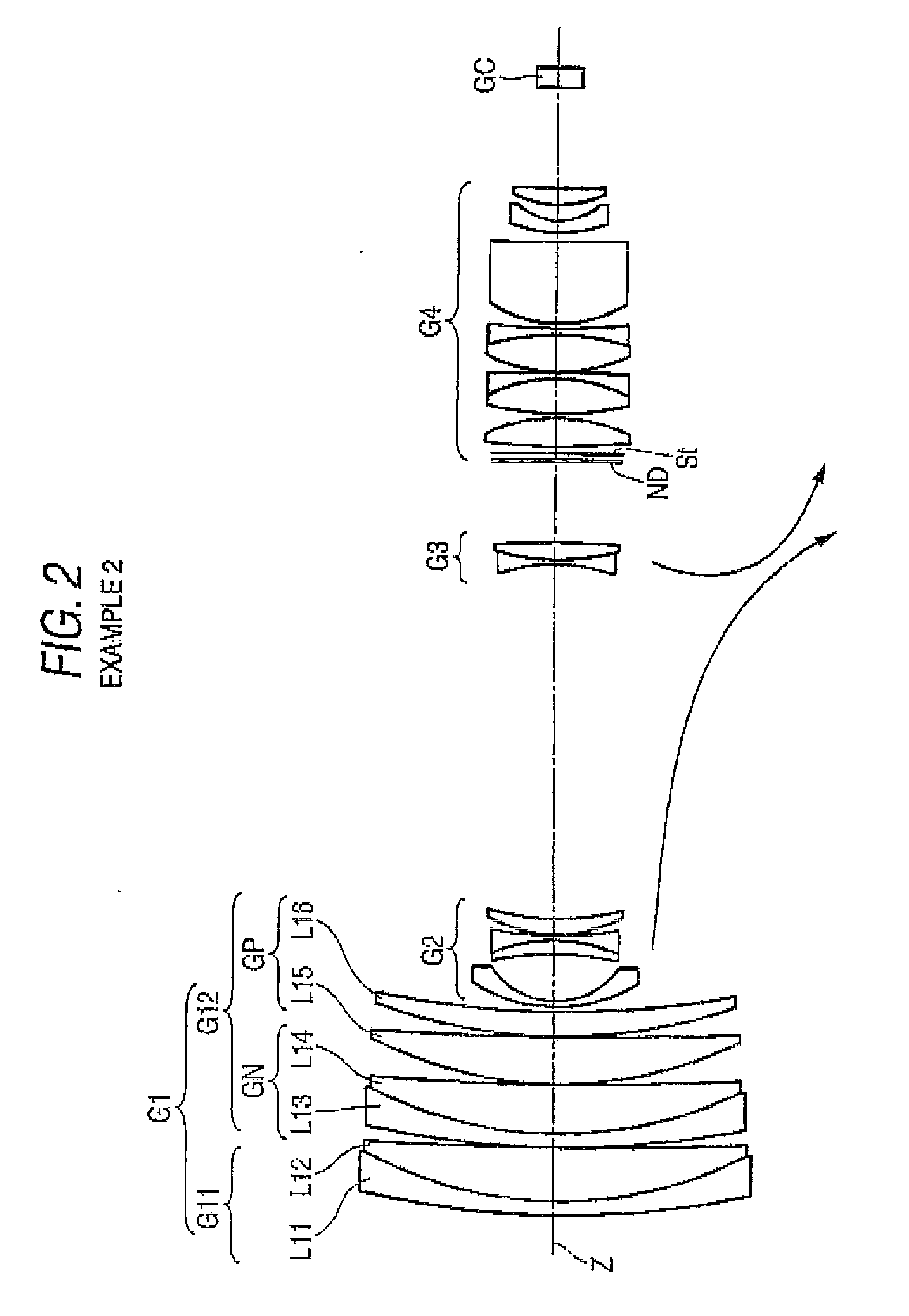
[0017]The stationary group of the zoom lens of the invention corresponds to the first group as described in the section of problems that the invention is to solve, and comprises a first lens group having a positive refractive power, a negative lens group having a negative refractive power and a positive lens group having a positive refractive power in order from an object side, as seen in groups by noting the refractive power. The stationary group before the variable power group may usually have a power arrangement of positive, positive and positive to make the focal length shorter, but the power arrangement of positive, negative and positive as in this invention can make the power of each group stronger than where all the groups are positive, and can make the refractive power of each lens stronger. Hence, since there is greater degree of freedom for allocating the refractive power of each lens suitably, it is more beneficial for the aberration correction. More particularly, the longitudinal chromatic aberration containing the residual secondary spectrum which is the concern in realizing the zoom lens of small size and the aberration at the reference wavelength can be corrected in well-balanced manner.

Problems solved by technology

However, if the higher variable power ratio is obtained simply by making the focal length of each lens group shorter, a large aberration variation is caused by the variable power, whereby it is very difficult to obtain a high optical performance over the entire variable power range.
Especially if the focal length of the first group is shorter, there was a problem that the residual secondary spectrum of longitudinal chromatic aberration abruptly increases near the telescopic end at the time of variable power.
In the zoom lens for television camera or video camera, if the variation of chromatic aberration is greater, the image quality of color image is extremely degraded.

Method used


Image

  • Zoom lens and imaging device
  • Zoom lens and imaging device
  • Zoom lens and imaging device

Examples


example 1

[0087]

Surface dataSurface numberRiDiNdjνdj 1193.3212.801.7550052.3 286.50210.421.6180063.3 36398.9730.151.00000 4152.0742.701.8060940.9 575.20610.931.4387594.9 6825.5760.151.00000 769.9469.871.4970081.5 8404.031Variable D11.00000 927.8071.201.8348042.71014.5979.031.0000011−53.9812.811.8080922.812−29.4381.001.8040046.61374.7590.201.000001426.3713.191.8080922.81547.060Variable D21.0000016−34.3051.001.8040046.61748.6763.251.8051725.418−190.995Variable D31.0000019∞0.301.5163364.120∞1.301.0000021∞1.501.00000(aperture diaphragm)2254.3266.391.4970081.523−34.4051.001.000002464.7066.601.4970081.525−27.6311.301.8160046.626−258.9400.151.000002738.4906.511.4970081.528−36.8461.301.8160046.629194.3881.001.000003018.8605.491.4874970.23153.7794.891.000003219.9222.501.7725049.63311.71610.001.000003432.3772.961.5174152.435−136.59820.001.0000036∞4.001.5163364.1Image surface∞0.001.00000Various kinds of dataVariable power ratio 22.00Half angleof viewfD1D2D3FNo.(degree)Wide-angle end10.311.0080.4214.682....

example 2

[0088]

Surface dataSurface numberRiDiNdjνdj 1167.3222.801.7550052.3 277.23210.621.6180063.3 3637.2660.151.00000 4177.4592.701.8060940.9 579.1049.811.4387594.9 6512.1210.151.00000 777.0899.471.4970081.5 8676.5190.151.00000 999.3505.001.4970081.510169.814Variable D11.000001128.4631.201.8348042.71214.4629.511.0000013−54.9332.851.8080922.814−28.8441.001.8040046.61571.3480.201.000001625.8933.141.8080922.81745.741Variable D21.0000018−33.2201.001.8040046.61942.4843.411.8051725.420−216.680Variable D31.0000021∞0.301.5163364.122∞1.301.0000023∞1.501.00000(aperture diaphragm)24123.3085.731.4970081.525−31.7371.001.000002660.1596.991.4970081.527−29.0941.301.8160046.628−335.5280.151.000002930.9527.431.4970081.530−46.6891.301.8160046.631109.6001.001.000003223.79616.471.4874970.233821.7111.921.000003425.8922.501.7725049.63511.7973.111.000003619.6463.321.5174152.437339.80519.991.0000038∞4.001.5163364.1Image surface∞0.001.00000Various kinds of dataVariable power ratio 21.99Half angleof viewfD1D2D3FNo.(...

example 3

[0089]

Surface dataSurface numberRiDiNdjνdj 1124.9572.801.8160046.6 290.0821.201.00000 388.26510.701.4970081.5 4−2074.5270.151.00000 5139.4992.701.7858944.2 667.52711.021.4970081.5 7331.0630.151.00000 871.5418.221.4970081.5 9218.025Variable D11.000001029.1581.201.8348042.71113.9788.041.0000012−43.9572.781.8080922.813−25.5511.001.8040046.61498.9790.201.000001527.2053.121.8080922.81653.326Variable D21.0000017−35.3421.001.8040046.61854.0103.201.8051725.419−163.686Variable D31.0000020∞0.301.5163364.121∞1.301.0000022∞1.501.00000(aperture diaphragm)2353.1556.631.4970081.524−33.9621.001.000002574.2596.611.4970081.526−27.1361.301.8160046.627−196.5570.151.000002841.1736.741.4970081.529−33.7621.301.8160046.630222.1711.001.000003119.9295.271.4874970.23259.2186.671.000003319.7682.501.7725049.63412.03410.001.000003530.3513.091.5174152.436−142.45020.001.0000037∞4.001.5163364.1Image surface∞0.001.00000Various kinds of dataVariable power ratio 22.00Half angleof viewfD1D2D3FNo.(degree)Wide-angle end1...


PUM


Abstract

A zoom lens comprises: a stationary group that is stationary at the time of variable power; and a variable power group, disposed on an image side of the stationary group, that makes a variable power operation by moving in an optical axis direction at the time of variable power, wherein the stationary group comprises: a first lens group including a negative meniscus lens and a positive lens and having a positive refractive power as a whole; and a second lens group, disposed on the image side of the first lens group, including: a negative lens group including a negative meniscus lens and a positive lens; and a positive lens group including at least one positive lens, in order from an object side, the second lens group having a positive refractive power as a whole.

Description

BACKGROUND OF THE INVENTION[0001]1. Field of the Invention[0002]The present invention relates to a zoom lens and an imaging device, and more particularly to a zoom lens which is suitable to be mounted on a television camera or video camera and an imaging device having the zoom lens.[0003]2. Description of the Related Art[0004]In the related art, a zoom lens of four group constitution mounted on the television camera or video camera is well known. The zoom lens of four group constitution has a first group having a positive refractive power, a second group having a negative refractive power and becoming a variable power group by moving at the time of variable power, a third group having a positive or negative refractive power and correcting a variation in the image point position caused by the variable power, and a fourth group having a positive refractive power in order from an object side, for example.[0005]In JP-B-7-1337, a zoom lens which comprises a first group having a positive ...

Claims


Application Information

Patent Timeline
Patent Type & Authority Applications(United States)
IPC IPC(8): G02B15/14
CPCG02B15/173G02B15/144113
Inventor TSUTSUMI, KATSUHISA
Owner FUJI PHOTO OPTICAL CO LTD
Why Eureka
Eureka Blog
Learn More