Biochip imaging method splitted with laser cofocus scanning combined image and its device

A biochip, confocal scanning technology, applied in biochemical equipment and methods, microbial determination/inspection, optics, etc., can solve the problem of difficulty in obtaining high optical resolution and fluorescence collection efficiency, complex optical design, and numerical aperture. problems such as small size, to achieve the effect of improving optical resolution and fluorescence collection efficiency, small size, and large numerical aperture

Inactive Publication Date: 2006-06-28
ZHEJIANG UNIV +1
View PDF5 Cites 15 Cited by
  • Summary
  • Abstract
  • Description
  • Claims
  • Application Information

AI Technical Summary

Problems solved by technology

The main advantage of the second type of device is that the vibration mirror has a small moment of inertia, low noise, and the scanning speed can reach above 50Hz; the main disadvantage is that the large field of view objective lens must ensure the imaging quality of the on-axis point and the off-axis point at the same time, and the optical design is complicated. Long focal length and small numerical aperture make it difficult to obtain high optical resolution and fluorescence collection efficiency

Method used


Image

  • Biochip imaging method splitted with laser cofocus scanning combined image and its device

Examples


Embodiment Construction

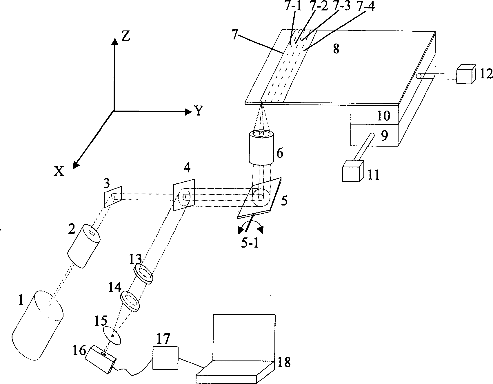
[0015] refer to figure 1 , the device of the biochip imaging method combining laser confocal scanning with image mosaic, including laser 1, beam expander 2, reflection mirror 3, dichromatic mirror 4, vibrating mirror 5, flat-field objective lens 6, fluorescent color filter 13, converging Mirror 14, has the confocal aperture 15 of aperture, photodetector 16 and the platform 8 that is used to place biochip 7, is provided with guide rail 9 and guide rail 10, the screw mandrel of guide rail 9 and the first motor at the bottom of platform 8 The 11 shafts are connected, the screw rod of the guide rail 10 is connected to the second motor 12 shafts; the laser 1, the beam expander 2, the reflector 3, the dichromatic mirror 4, the vibrating mirror 5, and the flat field objective lens 6 are arranged in sequence to form a biochip 7 The laser scanning optical path, the vibrating mirror 5 is located at the front focal plane of the flat-field objective lens 6, and the biochip 7 is located at...


PUM


Abstract

A biological chip imaging device with laser confocal scan integrated on image splicing is prepared as dividing biological chip to be multiple sub regions as each sub regional one ¿C dimensional scan being finalized by optical scanning formed with vibration mirror and planar field objective lens, and another dimensional being finalized by mechanical scanning formed with motor and guide track; converting fluorescent signal to be electric signal by photoelectric detector; using computer to collect and rebuild fluorescent image of current sub region; doing the same operation as above for each sub region then using computer to splice each fluorescent image for obtaining complete fluorescent image of biological chip.

Description

technical field [0001] The invention relates to a biochip fluorescence imaging method and a device thereof, in particular to a biochip imaging method and a device thereof using laser confocal scanning combined with image splicing. Background technique [0002] The biochip fluorescence imaging method based on laser confocal scanning can be divided into two categories according to the scanning method: the first category is to fix the mirror and small field of view objective lens in a scanning head, and the scanning head scans the biochip quickly along a certain direction; The second type is to use a large field of view objective lens. The laser beam is incident on the objective lens at different angles. The objective lens converts the angular scanning of the laser beam into a linear scanning along a certain direction of the biochip. U.S. Patent Nos. 5,459,325 and 6,407,858 both describe the first type of scanning device. The former fixes the mirror and the microscopic objectiv...

Claims


Application Information

Patent Timeline
Patent Type & Authority Applications(China)
IPC IPC(8): G01N21/64C12Q1/00G02B21/00
Inventor 王立强吴碧珍
Owner ZHEJIANG UNIV
Why Eureka
Try Eureka