Zoom lens and imaging apparatus

a zoom lens and imaging apparatus technology, applied in the field of small zoom lens and imaging apparatus, can solve the problems of insufficient miniaturization, inability to achieve high-quality images, and long overall length of the zoom lens, and achieve the effect of higher quality and quality

Inactive Publication Date: 2008-02-21
FUJI PHOTO OPTICAL CO LTD
View PDF2 Cites 16 Cited by
  • Summary
  • Abstract
  • Description
  • Claims
  • Application Information

AI Technical Summary

Benefits of technology

[0014]In the zoom lens according to an aspect of the invention, in addition, the second lens group preferably has a two-group, three-lens configuration which consists of: in order from the object side, a cemented lens consisting of a double convex lens and a negative lens having a concave surface on the object side; and a positive single lens having at least one aspherical surface. By this configuration, the zoom lens becomes more advantageous in correction of the aberrations, whereby images with much higher quality can be held.
[0015]Furthermore, a shape of the aspherical surface of the first lens group is preferably defined by an aspheric coefficient which includes a coefficient in an odd-order term. In addition, the shape of the aspherical surface of the first lens group is preferably defined by an aspheric coefficient which includes a coefficient in a 16-th or more order term. By these configurations, the resulting zoom lens becomes more advantageous in correction of the aberrations, whereby images with much higher quality can be held.

Problems solved by technology

In the zoom lenses described in the patent publications above, however, since the focal length of the whole of a first lens group is made longer or the thickness of the whole of the first lens group is made thicker, the overall length of the zoom lens tends to be long, and the miniaturization has not yet been attained sufficiently.
In addition, in the event that a further miniaturization is attempted to attained based on the configuration of the zoom lens described in each of the aforesaid patent documents, the formation of images with higher quality cannot be realized.
In addition, in JP-A-2003-149556, since a surface of the second lens group which lies closest to the object is made aspherical and this aspherical lens is made to constitute a cemented lens, the aspherical surface cannot be provided only on one surface, leading to an issue that among aberrations, in particular, spherical aberration cannot be corrected sufficiently.
In addition, in the configuration of JP-A-2006-39523, since a second lens group is made up of a cemented lens which is made up by cementing three lenses together, the degree of freedom in design is reduced, and the correction of, in particular, spherical aberration is made difficult.
In addition, in the configuration of JP-A-2006-84829, since the focal length of a second lens group which constitutes a primary variable power or focal length varying portion is long, the overall length of the zoom lens becomes long, whereby the miniaturization is made difficult to be realized.
In addition, in the configuration of JP-A-2006-23678, since a second lens group is made up of two lenses; a positive lens and a negative lens, the correction of on-axis chromatic aberration is made difficult.

Method used


Image

  • Zoom lens and imaging apparatus
  • Zoom lens and imaging apparatus
  • Zoom lens and imaging apparatus

Examples


examples

[0064]Next, specific numerical examples of the zoom lens according to the embodiment will be described below. In the description below, based on the first embodiment of the invention, first to fourth numerical examples will be described altogether.

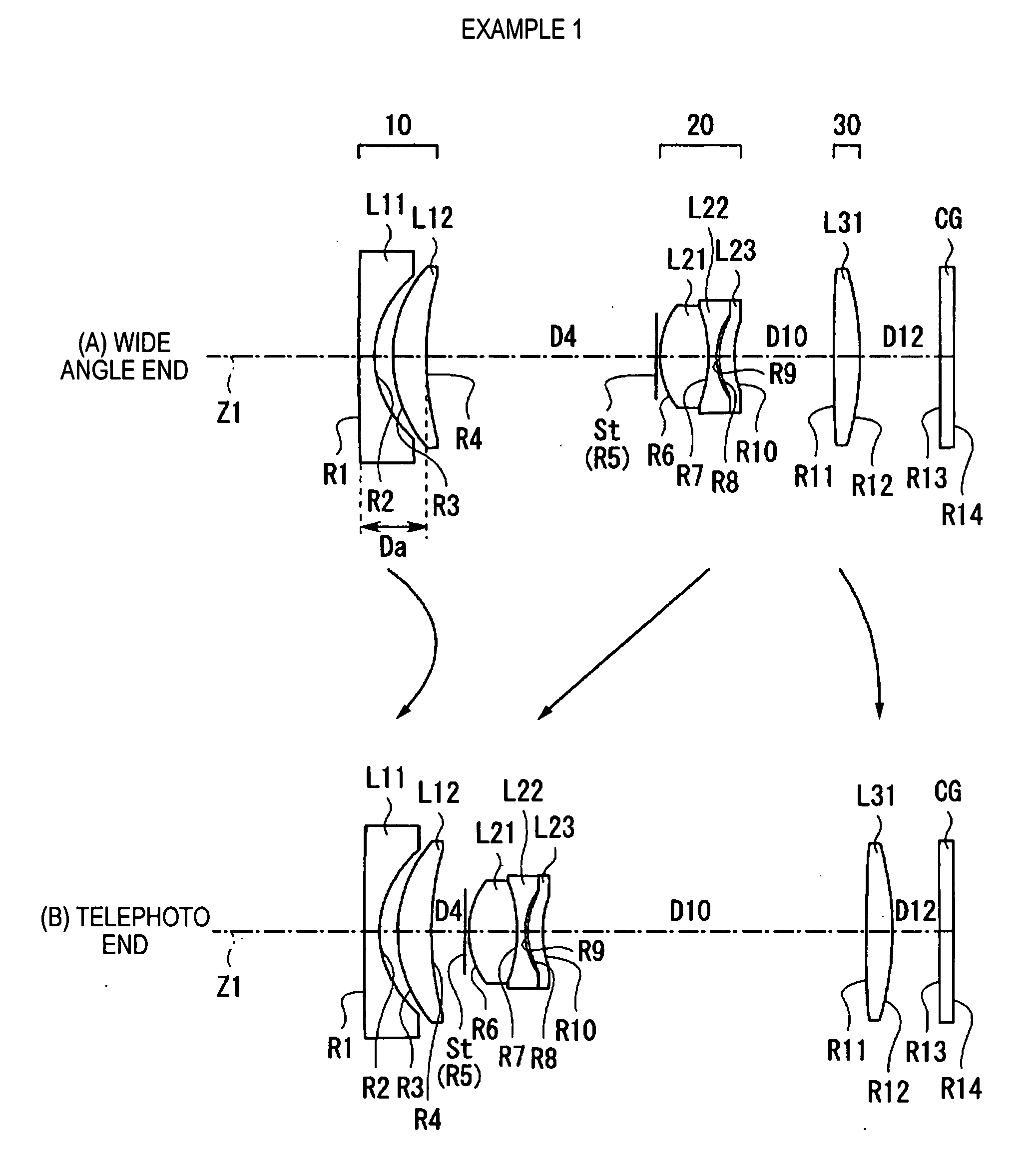
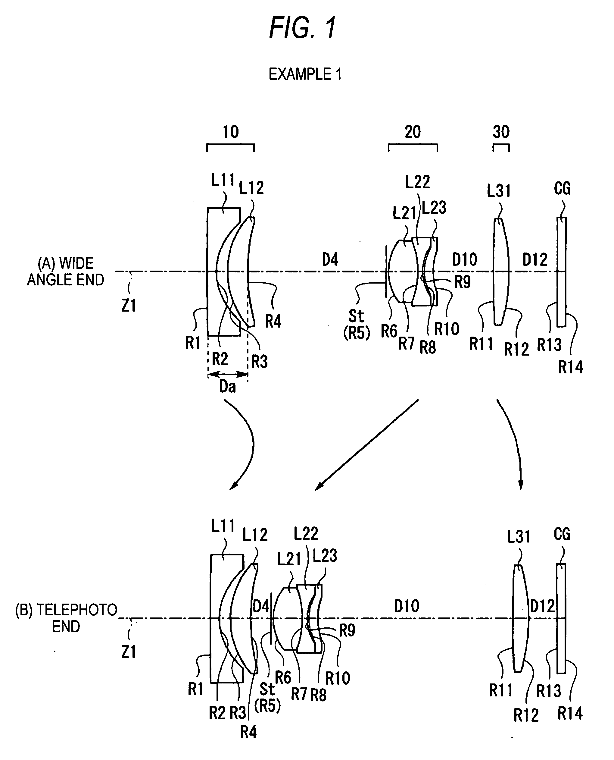
[0065]FIGS. 5(A), 5(B) and 6 show specific lens data (Example 1) which corresponds to the configuration of the zoom lens shown in FIG. 1. In particular, lens data thereof is shown in FIG. 5(A), data related to zooming is shown in FIG. 5(B), and data related to aspherical surfaces is shown in FIG. 6.

[0066]Shown in a column of Si (surface number) in the lens data shown in FIG. 5(A) are numbers of i-th (i=1 to 14) surfaces which result when symbols are given to surfaces of constituent lenses of a zoom lens of this example in such a manner as to increase sequentially from an object side surface of a constituent lens situated on closest to as the first surface, toward an image side of the zoom lens. Shown in a column of Ri (radius of curvature)...


PUM


Abstract

A zoom lens is provided and includes: in order from an object side thereof, a first lens group having a negative refractive power, a stop; a second lens group having a positive refractive power; and a third lens group having a positive refractive power. The magnification of the zoom lens is varied from a wide angle end to a telephoto end by changing a space between the first lens group and the second lens group and a space between the second lens group and the third lens group. The first lens group includes: in order from an object side thereof, a negative lens having at least one aspherical surface and having a concave surface on an image side thereof; and a positive meniscus lens having a convex surface on the object side thereof. The zoom lens satisfies conditional expressions specified in the specification.

Description

BACKGROUND OF THE INVENTION[0001]1. Field of the Invention[0002]The present invention relates to a small zoom lens and an imaging apparatus which are preferably used for a video camera, a digital still camera and the like.[0003]2. Description of Related Art[0004]As a zoom lens for use in a video camera, a digital still camera and the like, for example, known is a three-group zoom lens in which the magnification is varied by moving lens groups along an optical axis so as to change spaces between the respective lens groups. In recent years, in imaging optical systems like this, there has been an increasing demand for optical systems which are smaller in size and are able to form images with higher quality. JP-A-2003-149556, JP-A-2006-39523, JP-A-2006-84829 and JP-A-2006-23678 propose techniques in which the whole optical system of a three-group zoom lens is made smaller in size while being configured to form images with higher quality by arranging refractive powers of the lens groups ...

Claims


Application Information

Patent Timeline
Patent Type & Authority Applications(United States)
IPC IPC(8): G02B15/14
CPCG02B15/177G02B15/143507
Inventor ORI, TETSUYA
Owner FUJI PHOTO OPTICAL CO LTD
Why Eureka
Try Eureka