Head-mounted display device and optical lens system thereof

A technology of optical lens and display screen, applied in optics, optical components, instruments, etc., can solve the problems of small working distance from eyepiece to display screen and unsatisfactory use, and achieve the effect of excellent imaging quality and guaranteed field of view

Active Publication Date: 2015-11-18
宿州飞目光电科技有限公司
View PDF8 Cites 16 Cited by
  • Summary
  • Abstract
  • Description
  • Claims
  • Application Information

AI Technical Summary

Problems solved by technology

For micro-displays such as LCOS (Liquid Crystalon Silicon, Chinese is: liquid crystal with silicon) display and DLP (Digital Light Procession, Chinese is: digital light processing) display, it is necessary to place the necessary lighting system between the display and the eyepiece; The working distance of the display screen is mostly small, which cannot meet the needs of the use

Method used


Image

  • Head-mounted display device and optical lens system thereof
  • Head-mounted display device and optical lens system thereof
  • Head-mounted display device and optical lens system thereof

Examples


Embodiment 1

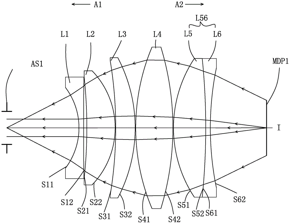
[0072] refer to figure 1 As shown, the optical lens system of this embodiment includes sequentially along an optical axis I from the light exit side A1 to the light entrance side A2: an aperture stop AS1, a first lens L1, a second lens L2, a The third lens L3, a fourth lens L4, a fifth lens L5, and a sixth lens L6. Each lens has a spherical lens with refractive power, and has a first surface facing the light-emitting side A1 and allowing the light to pass through, and a second surface facing the light-incident side A2 and allowing the light to pass through.

[0073] The first lens L1, the second lens L2, the third lens L3, the fourth lens L4, the fifth lens L5 and the sixth lens L6 of the optical lens system of this embodiment are exemplarily made of glass or plastic materials, And the detailed structure is formed as follows:

[0074] The aperture (aperture stop) AS1 is an equivalent aperture, and the entity of this part may not be provided in practical application. The pos...

Embodiment 2

[0091] refer to Figure 5 As shown, the optical lens system of this embodiment includes sequentially along an optical axis I from the light exit side A1 to the light entrance side A2: an aperture stop AS1, a first lens L1, a second lens L2, a The third lens L3, a fourth lens L4, a fifth lens L5, and a sixth lens L6. Each lens has a spherical lens with refractive power, and has a first surface facing the light-emitting side A1 and allowing the light to pass through, and a second surface facing the light-incident side A2 and allowing the light to pass through. In order to make the drawings more concise, only the numbers on the surfaces different from those in Embodiment 1 are marked in the drawings of this embodiment, which is the case for the following embodiments, and will not be repeated here.

[0092] The surface design of each lens in this embodiment is basically the same as that in Embodiment 1, except that the second surface S12 of the first lens L1 in this embodiment is...

Embodiment 3

[0100] refer to Figure 9 As shown, the optical lens system of this embodiment includes sequentially along an optical axis I from the light exit side A1 to the light entrance side A2: an aperture stop AS1, a first lens L1, a second lens L2, a The third lens L3, a fourth lens L4, a fifth lens L5, and a sixth lens L6. Each lens has a spherical lens with refractive power, and has a first surface facing the light-emitting side A1 and allowing the light to pass through, and a second surface facing the light-incident side A2 and allowing the light to pass through.

[0101] The surface design of each lens in this embodiment is basically the same as that in Embodiment 1, except that the second surface S12 of the first lens L1 in this embodiment is convex, and the second surface S62 of the sixth lens L6 is flat. In addition, the radius of curvature of each lens of this embodiment and the thickness of the lens on the optical axis are slightly different from those of Embodiment 1. In th...


PUM


Abstract

The invention relates to a head-mounted display device and an optical lens system thereof. The optical lens system comprises a first lens, a second lens, a third lens, a fourth lens, a fifth lens and a sixth lens which are arranged in sequence from a light inlet side to a light outlet side along an optical axis, wherein each lens is a spherical lens with an refractive index, the first lens is a negative focal power lens, the second lens is a positive focal power lens, the third lens is a positive focal power lens, the fourth lens is a positive focal power lens, the fifth lens is a positive focal power lens, and the sixth lens is a negative focal power lens. The head-mounted display device provided by the invention comprises a machine shell and a display module which is installed in the machine shell, wherein the display module comprises at least one optical lens system disclosed in the invention and at least one display screen which is arranged on an optical axis, facing the light inlet side, of a second surface of the sixth lens. The head-mounted display device and the optical lens system thereof ensure angle of field of view, ensure good imaging quality, and have the advantages of short focal length and long working distance.

Description

technical field [0001] The present invention relates to a head-mounted display device and its optical lens system, and in particular to a head-mounted display device using a six-piece lens and its optical lens system. Background technique [0002] In recent years, due to the rise of wearable electronic devices, miniaturized display modules including optical lens systems and microdisplays have flourished, and are widely used in head-mounted display devices. Head-mounted display devices are widely used in military, aerospace, medical, entertainment, simulation training and other fields. In terms of entertainment, a suitable viewing angle can create a shocking visual effect for users, making users feel as if they are in the best position in the projection hall of a movie theater to watch movies. [0003] In the prior art, CN104570323A proposes a head-mounted eyepiece system and a head-mounted display device. The eyepiece system adopts 4 lenses, and the imaging definition canno...

Claims


Application Information

Patent Timeline
Patent Type & Authority Applications(China)
IPC IPC(8): G02B27/01G02B13/00
CPCG02B13/0015G02B27/0172G02B2027/0123
Inventor 江虹叶龙
Owner 宿州飞目光电科技有限公司
Why Eureka
Try Eureka