Tip hood member

一种顶端罩、顶端部的技术,应用在彩色电视的零部件、电视系统的零部件、光学元件等方向,能够解决患者不适感、难以变形、难以将罩等问题

Inactive Publication Date: 2009-05-06
OLYMPUS CORP
View PDF5 Cites 0 Cited by
  • Summary
  • Abstract
  • Description
  • Claims
  • Application Information

AI Technical Summary

Problems solved by technology

[0006] However, in the endoscope described in Japanese Patent Application Laid-Open No. 2001-224550, the cover is substantially cylindrical and difficult to deform. Therefore, when force is applied from the distal end side of the cover, the force is concentrated on the protruding part of the cover or toward the In order to prevent the damage of the cover caused by such force on the mounting part of the endoscope, the material of the cover must be a highly durable and expensive material
In addition, in order to prevent the cover from deviating or falling off from the mounting portion of the endoscope due to such force, the structure of mounting the cover on the mounting portion of the endoscope is complicated, and it is difficult to place the cover when repairing or maintaining the endoscope. Questions such as removal
[0007] In the technique described in Japanese Patent Application Laid-Open No. 59-93413, a cutout is provided on a part of the cover, and the cover deforms in response to a force applied from the outer peripheral direction of the cover. Deformation due to the force applied to the tip side of the head, the same problem as the technology described in Japanese Patent Laid-Open No. 2001-224550
[0008] In addition, if the strength of the cover is increased, the operator must be careful not to cause discomfort to the patient when inserting it into the body cavity.
However, since the force of deformation of the cover due to the force from the tip side of the cover is not considered at all, there is still a possibility that the patient may feel uncomfortable.

Method used


Image

  • Tip hood member
  • Tip hood member
  • Tip hood member

Examples


no. 1 Embodiment approach

[0040] figure 1 ~ Fig. 5 shows the first embodiment of the present invention.

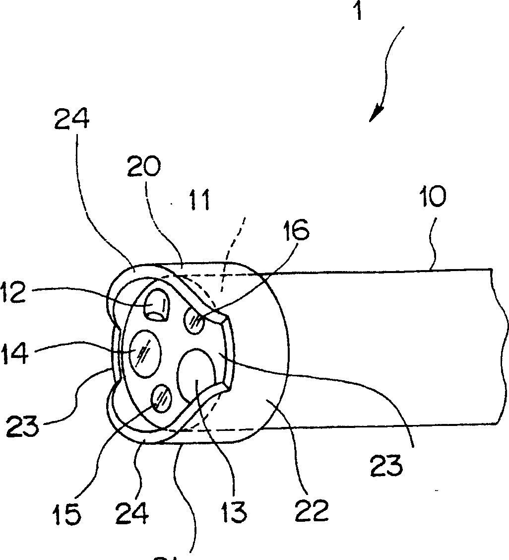
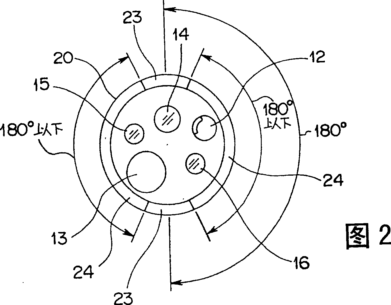
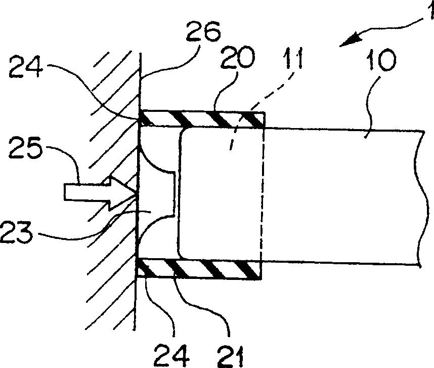
[0041] Such as figure 1 As shown, the endoscope 1 together with a light source device (not shown), an image processor, and a monitor constitute an endoscope device. On the distal end portion 11 of the insertion portion 10 of the endoscope 1, a distal end cover member 20 is provided in a detachable state. In this case, the tip cover member 20 is formed in a substantially cylindrical shape, and is press-fitted and fixed to the tip portion 11 .

[0042] The tip cover member 20 is formed of a soft and elastic soft material such as vulcanized rubber such as silicone rubber and fluororubber, or thermoplastic elastomer such as polyurethane elastomer, acrylic elastomer, or olefin elastomer.

[0043] The distal end cover member 20 has a protruding portion 21 protruding from the distal end portion 11 and an endoscope fixing portion 22 fitted with the distal end portion 11 . Two recesses 23 , 23 are provi...

no. 2 Embodiment approach

[0063] Figure 6 ˜ FIG. 8 show a second embodiment of the present invention.

[0064] Such as Figure 6 As shown, the endoscope 3 of this embodiment differs from the first embodiment shown in FIG. 2 only in the tip cover member 30, and the insertion portion 10 has the same structure as that of the first embodiment.

[0065] The distal cover member 30 is formed of the same material as that of the distal cover member 20 of the first embodiment. The protruding portion 31 of the distal end cover member 30 is provided with recesses 33 at four places so that the protruding portion 31 can deform when a force is applied from the tip of the protruding portion 31 .

[0066] In this case, the recesses 33 are provided at intervals of 90°. Four convex portions 34 are formed by forming four concave portions 33 on the protruding portion 31 .

[0067] Such as Figure 7 As shown, the observation depth of the observation optical system 14 is set to 3 mm to 100 mm. The protrusion amount h1...

no. 3 Embodiment approach

[0074] Figure 9 The third embodiment of the present invention is shown.

[0075] Such as Figure 9 As shown, in the endoscope 4 of this embodiment, the observation depth of the observation optical system 44 provided on the distal end portion 41 of the insertion portion 40 is set to 4 mm to 100 mm.

[0076] The distal cover member 50 is formed of the same material as that of the distal cover member 20 of the first embodiment.

[0077] On the protruding portion 51 of the tip cover member 50, four recessed portions 53 are provided at intervals of 90°. The protruding portion 51 is formed with four convex portions 54 via four concave portions 53 . On the inner peripheral surface of the convex portion 54, a tapered portion 56 having a shape expanding toward the distal end side is provided.

[0078] The protrusion amount h3 of the convex portion 54 from the observation optical system 44 is set to be substantially the same as the near-point value b=4 mm of the observation depth. ...


PUM


Abstract

In the present invention, a distal hood component 20 is detachably provided at the distal end 11 of an insertion portion 10 of an endoscope 1. The distal hood component 20 is formed from a soft, elastic soft material. The distal hood component 20 includes a protrusion 21 protruding from the distal end 11 and an endoscope fixation portion 22 into which the distal end 11 is fitted. Convex portions 24 and 24 and concave portions 23 and 23 are provided on the protrusion 21. The shapes of the convex portions 24 and 24 and concave portions 23 and 23 are adjusted in order that the convex portions 24 and 24 of the protrusion 21 are deformed by a force of 0.29 Mpa or less applied from the end of the protrusion 21.

Description

technical field [0001] The present invention relates to a distal end cover member provided at a distal end portion of an insertion portion of an endoscope. Background technique [0002] Conventionally, as an example of an endoscope device used for surgery, an observation optical system, a light guide, an air / water delivery port, and a suction port are provided at the distal end of the insertion portion of the endoscope. In such an endoscope device, light is irradiated from a light guide to a subject such as biological tissue, the subject irradiated by the light is recognized through the objective lens, and air or water or water sent from the air / water delivery port is sucked in through the suction port. other substances. [0003] Furthermore, as an endoscope apparatus, in order to ensure the closest distance between the observation window of the observation optical system and the subject, a cover is provided at the distal end of the insertion portion of the endoscope. [0...

Claims


Application Information

Patent Timeline
Patent Type & Authority Patents(China)
IPC IPC(8): A61B1/00G02B23/24H04N5/225
CPCA61B1/00089A61B1/0008A61B1/00A61B1/00101
Inventor 石引康太
Owner OLYMPUS CORP
Why Eureka
Try Eureka