Resin inner member-provided grommet

a technology of inner member and spherical member, which is applied in the direction of insulated conductors, cables, cables, etc., can solve the problems of pressing waste, and achieve the effect of improving waterproof and dustproof performan

Inactive Publication Date: 2005-06-07
SUMITOMO WIRING SYST LTD
View PDF15 Cites 44 Cited by
  • Summary
  • Abstract
  • Description
  • Claims
  • Application Information

AI Technical Summary

Benefits of technology

[0015]The present invention overcomes the above-described shortcomings of the prior art. Accordingly, it is an object of the present invention to increase a fitting force of a resinous inner member on a large-diameter cylindrical part of the body of a gromm

Problems solved by technology

Thus, there is waste

Method used


Image

  • Resin inner member-provided grommet
  • Resin inner member-provided grommet
  • Resin inner member-provided grommet

Examples


Embodiment Construction

[0064]The following description of the preferred embodiment(s) is merely exemplary in nature and is in no way intended to limit the invention, its application, or uses.

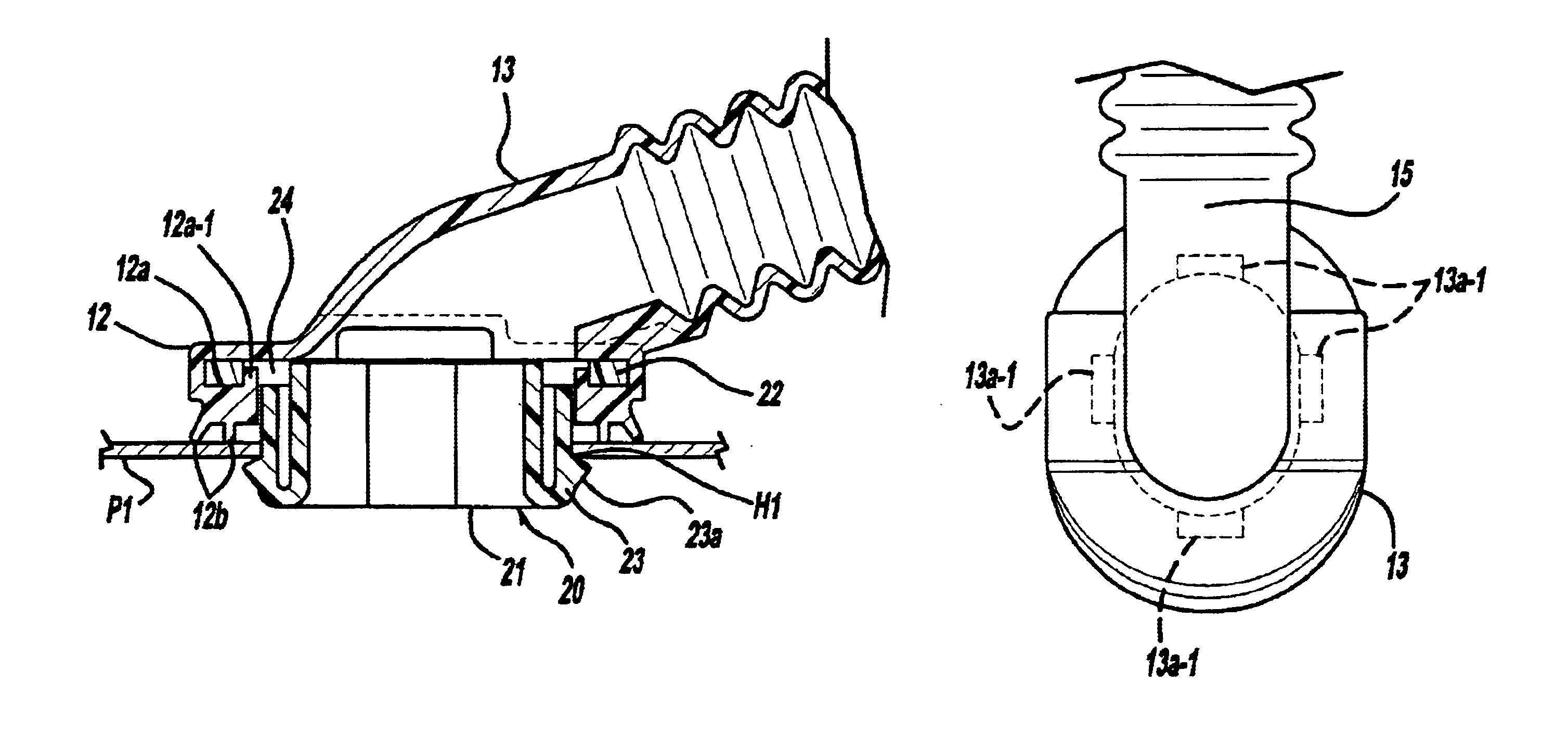
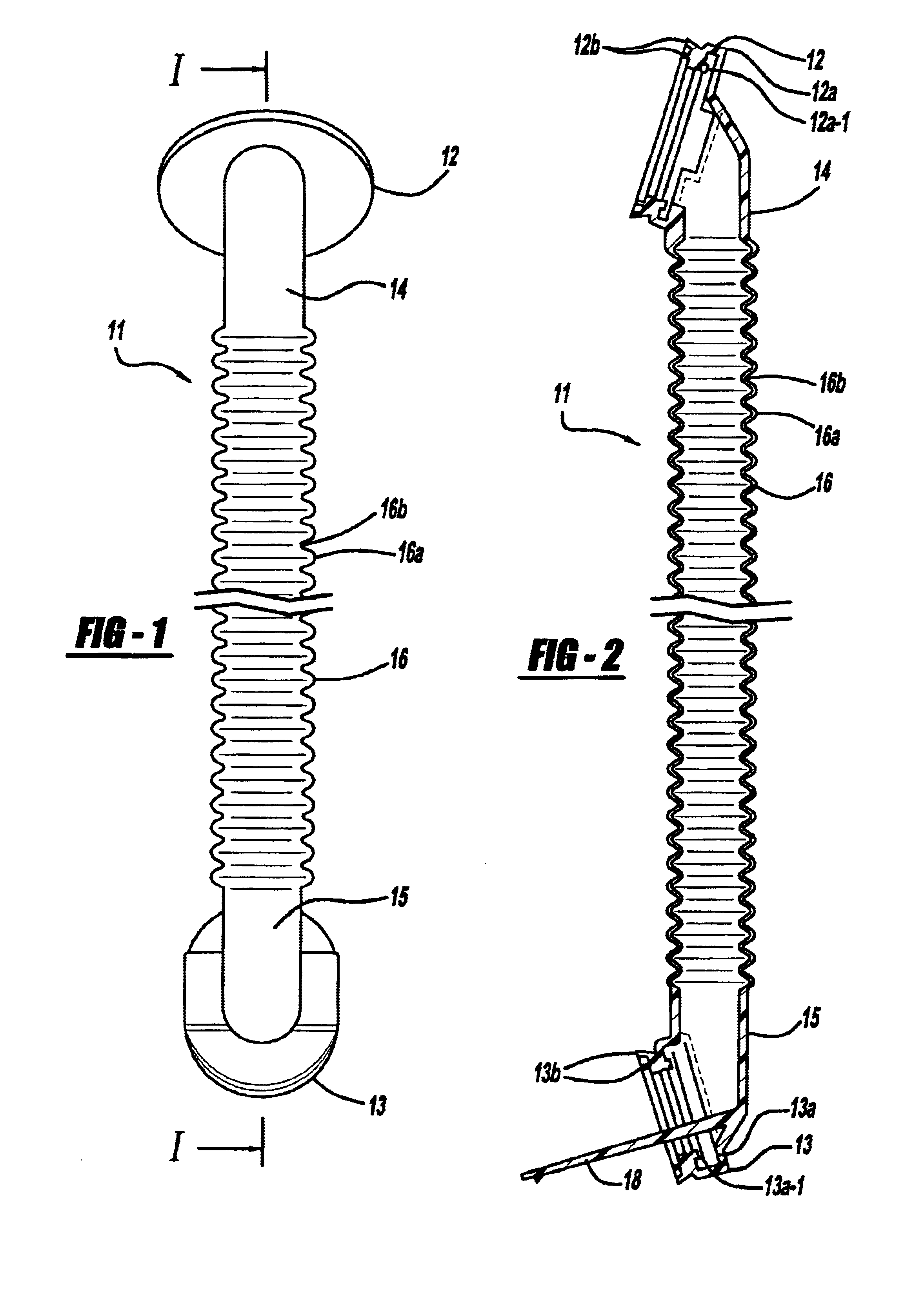
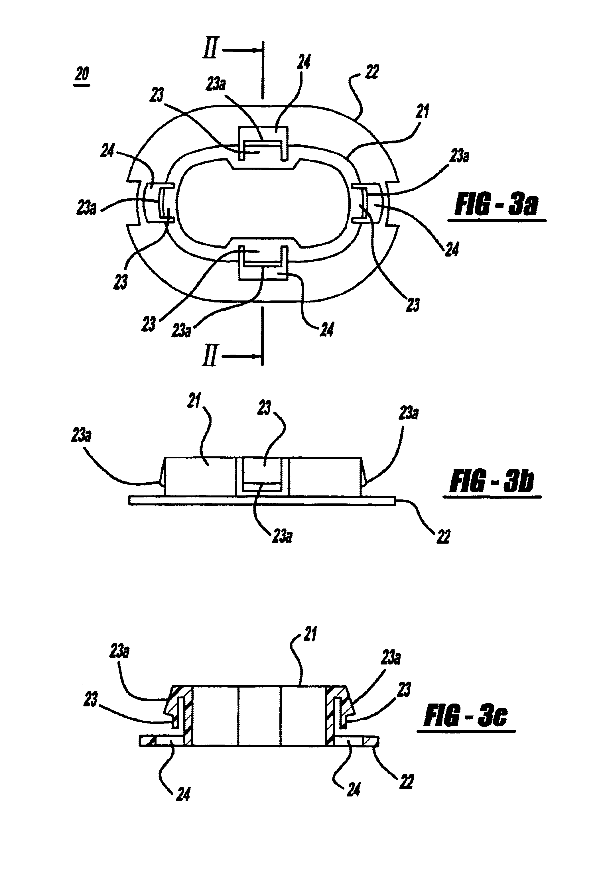
[0065]The grommet according to the invention is installed between a body panel P and a door panel P2 as shown in FIG. 6. A wire harness is inserted into the grommet. The grommet has a body 11 and a resinous inner member 20, installed on the body 11.

[0066]The body 11 has a bellow-shaped cylindrical part 16. The bellow-shaped cylindrical part 16 has alternating mountain portions 16a and valley portions 16b. Small-diameter cylindrical parts 14 and 15 are continuous with respective ends of the bellow-shaped cylindrical part 16. Large-diameter cylindrical parts 12 and 13 are continuous with the small-diameter cylindrical parts 14 and 15, respectively. The body 11 is made of rubber or elastomers integrally molded to shape.

[0067]The large-diameter cylindrical parts 12 and 13 have annular concavities 12a and 13a for locking t...


PUM


Abstract

A locking claw (23a) to be locked to a through-hole (H) projects outwardly from a peripheral wall (21) of a resinous inner member (20). At least one pair of locking holes (24) is formed on a locking flange part (22) projecting from the peripheral wall (21). An annular concavity (12a) (13a), on which the locking flange part (22) fits, is formed on an inner peripheral surface of a large-diameter cylindrical part (12, 13). Locking projections (12a-1, 13a-1) project from a leading end of a side wall of the annular concavity (12a, 13a). The locking projections (12a-1, 13a-1) are inserted into and locked with the locking holes (24). Locking claws (123a-126a) project from the resinous inner member (120) and are locked to a through-hole (H1) of the body panel (P1). A pair of flexible locking pieces (123-126), to be locked to the body panel (P1), project from each of a shorter side and a longer side of an elliptic peripheral wall (121) of the resinous inner member (120) projecting from an open end of the large-diameter cylindrical part (112, 113). A leading end of the locking pieces (123-126) project outwardly from an intermediate position of an outer surface of the locking pieces (123-126). The locking pieces on the longer side are curved longitudinally to form a circular arc shape.

Description

CROSS-REFERENCE TO RELATED APPLICATIONS[0001]This application claims priority to Japanese Patent Application Nos. JP 2001-305282 and JP 2001-323036 filed Oct. 1, 2001 and Oct. 22, 2001, respectively, which applications are herein expressly incorporated by reference.FIELD OF THE INVENTION[0002]The present invention relates to a resinous inner member-provided grommet. More particularly, the present invention is intended to securely bring an open end of a large-diameter cylindrical part of the body of the grommet into close contact with a body panel of a vehicle. This improves the waterproof performance and dustproof performance of the grommet. Also, the resinous inner member-provided grommet can be inserted into a through-hole of a door panel with a small force to lock the resinous inner member-provided grommet into the through-hole.BACKGROUND OF THE INVENTION[0003]A wire harness to be wired on a vehicle body is inserted into a resinous inner member-provided grommet mounted on a throu...

Claims


Application Information

Patent Timeline
IPC IPC(8): B60R16/02F16L37/00H02G3/02H02G3/04H02G3/06
CPCB60R16/0222F16L37/008H02G3/0616H02G3/0468Y10T16/063Y10T16/05H02G11/00H02G3/22
Inventor UCHIDA, YOSHIMI
Owner SUMITOMO WIRING SYST LTD
Why Eureka
Try Eureka