
Reverse self-locking mechanism of trigger switch

An anti-self-locking and trigger technology, applied in the direction of portable mobile devices, manufacturing tools, etc., can solve the problems of aggravated impact, failure of anti-self-locking mechanism, hidden safety hazards, etc., to increase service life, protect personal safety, and improve fluidity Effect

Active Publication Date: 2016-04-20
HANGZHOU KEMING ELECTRONICS CO LTD
View PDF7 Cites 0 Cited by
  • Summary
  • Abstract
  • Description
  • Claims
  • Application Information

AI Technical Summary

Problems solved by technology

[0002] As we all know, the anti-self-locking mechanism of most trigger switches used in the market (anti-self-locking means that the trigger cannot be pressed when the anti-self-locking mechanism is not pressed, that is, the switch or tool cannot be started) are basically in the The outside of the casing; when the power tool is being used for construction, the dust and debris generated are easy to attach to the surface of the switch. Since the anti-self-locking mechanism is outside the casing, the dust and debris generated during construction are anti-self-locking. The influence of the normal action of the mechanism is intensified, which will easily lead to the failure of the anti-self-locking mechanism and cause safety hazards

Method used


Image

  • Reverse self-locking mechanism of trigger switch
  • Reverse self-locking mechanism of trigger switch
  • Reverse self-locking mechanism of trigger switch

Examples


Embodiment 1

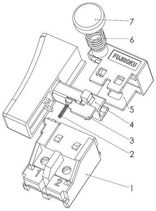
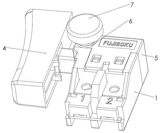
[0022] see Figure 1~2 , in an embodiment of the present invention, an anti-self-locking mechanism of a trigger switch includes a casing 1, a casing 5 and a trigger 4, the trigger 4 is installed between the casing 1 and the casing 5, and an anti-self-locking mechanism is movably installed on the casing 5 device, the anti-self-locking device includes a limiting groove in the casing 1 and a locking plate 3, the limiting groove is opened in the casing 1, the locking plate 3 is movably installed in the limiting groove inside the casing 1, and the locking plate 3 is It is limited in the limit groove in the casing 1, and can move up and down, and control the movement of the trigger 4. The locking plate 3 and the casing 1 work together to control the trigger 4 to realize the anti-self-locking function.

[0023] The outside of shell 5 is equipped with the anti-self-locking button 7 that controls anti-self-locking device, and the anti-self-locking resetting device that is connected wit...

Embodiment 2

[0028] The shell of an anti-self-locking machine of a trigger switch is prepared according to the following method:

[0029] 1) Weigh each raw material by weight for later use: 1 part of gallium, 1 part of cerium, 1 part of neodymium, 2 parts of glass fiber, 3 parts of niobium, 3 parts of zirconium, 8 parts of zinc, 10 parts of graphite, 10 parts of titanium, and 30 parts of silicon parts, aluminum 80 parts, magnesium 1000 parts;

[0030] 2) Add glass fiber and graphite to acetone in sequence, stir at 100 rpm for 6 hours, and then refrigerate at 4°C for 12 hours to obtain auxiliary materials; wherein, the mass ratio of acetone to graphite is 2:1;

[0031] 3) Preheat gallium, cerium, neodymium, niobium, zirconium, zinc, titanium, silicon, aluminum and magnesium at 200°C for 1 hour;

[0032] 4) Use a crucible resistance furnace to melt the preheated magnesium, then add auxiliary materials, zinc, silicon and aluminum at 750 ° C, and stir the melt for 3 minutes; continue to heat ...

Embodiment 3

[0035] Comparative Experiment 1: The process steps are the same as in Example 2, except that graphite and glass fibers are not added.

[0036] Comparative Test 2: The process steps are the same as in Example 2, except that gallium, cerium, neodymium, niobium and zirconium are not added.


PUM


Abstract

The invention discloses a reverse self-locking mechanism of a trigger switch. The mechanism comprises a chassis, a housing, and a trigger which is mounted between the chassis and the housing, wherein a reverse self-locking device is movably mounted on the housing; a reverse self-locking button for controlling the reverse self-locking device is mounted at the outer side of the housing; a reverse self-locking returning device which is connected to the trigger is mounted between the reverse self-locking button and the housing; another reverse self-locking returning device is mounted between the trigger and the chassis; the reverse self-locking device comprises a limiting groove and a locking plate which are arranged in the chassis; the limiting groove is formed in the chassis; the locking plate is movably mounted into the limiting groove in the chassis. The reverse self-locking mechanism of the trigger switch is simple in structure; a reverse self-locking switch chassis and the locking plate are re-designed, namely, the locking plate is moved into the switch chassis, so that the reverse self-locking reliability can be achieved, and the switch chassis can be completely closed, and as result, the dust preventing performance can be effectively improved, and the personal safety of a user can be protected.

Description

technical field [0001] The invention relates to the field of trigger switch devices, in particular to an anti-self-locking mechanism of a trigger switch. Background technique [0002] As we all know, the anti-self-locking mechanism of most trigger switches used in the market (anti-self-locking means that the trigger cannot be pressed when the anti-self-locking mechanism is not pressed, that is, the switch or tool cannot be started) are basically in the The outside of the casing; when the power tool is being used for construction, the dust and debris generated are easy to attach to the surface of the switch. Since the anti-self-locking mechanism is outside the casing, the dust and debris generated during construction are anti-self-locking. The influence of the normal action of the mechanism is intensified, which will easily lead to the failure of the anti-self-locking mechanism and cause potential safety hazards. [0003] Due to the long-term exposure to the outdoors and the...

Claims


Application Information

Patent Timeline
IPC IPC(8): B25F5/02B23P15/00
CPCB23P15/00B25F5/02
Inventor 佐藤学喻圣君菊池祥骆建功姜洪刚
Owner HANGZHOU KEMING ELECTRONICS CO LTD
Learn More