Adjustable support foot

a technology of adjustable support and foot, which is applied in the direction of machine supports, furniture parts, other domestic objects, etc., can solve the problems of inconvenient adjustment of conventional support feet, unable to and the prior art adjustable support feet comprising a support pad and a bolt device can not meet the requirements of promoting work efficiency. , to achieve the effect of quick adjustment and quick adjustmen

Inactive Publication Date: 2005-06-07
HUANG SHIH YI
View PDF10 Cites 58 Cited by
  • Summary
  • Abstract
  • Description
  • Claims
  • Application Information

AI Technical Summary

Benefits of technology

[0005]Accordingly, the primary objective of the present invention is to provide an adjustable support foot whose height can be quickly adjusted. The adjustable support foot comprises a support post, a plurality of retaining plates, a control device and an outer shell. The support post is a cylindrical body provided with a screwed axle in its upper section and a cup base in its lower section. The retaining plates are provided with screw threads on the inner surfaces thereof. The screwed axle is covered by the retaining plates, and then enclosed within a control device that includes a retaining cylinder and a control ring. The control device can decouple the retaining plates from the screwed axle or reengage them together. An outer shell further encloses the control device. Thereby, the height of the adjustable support foot thus formed can be quickly adjusted.

Problems solved by technology

To adjust the height of the support foots, some of the support pads have to be rotated, which is rather time consuming.
For a user who needs to shift a stepladder or a frame structure around during operation, the adjustment of the conventional support foots appears rather inconvenient, especially when the stepladder or the frame structure is used on a rugged and rough ground.
Therefore, adjustable support foots of the prior art comprising a support pad and a bolt device cannot meet the requirement of promoting work efficiency.

Method used


Image

  • Adjustable support foot
  • Adjustable support foot
  • Adjustable support foot

Examples


Embodiment Construction

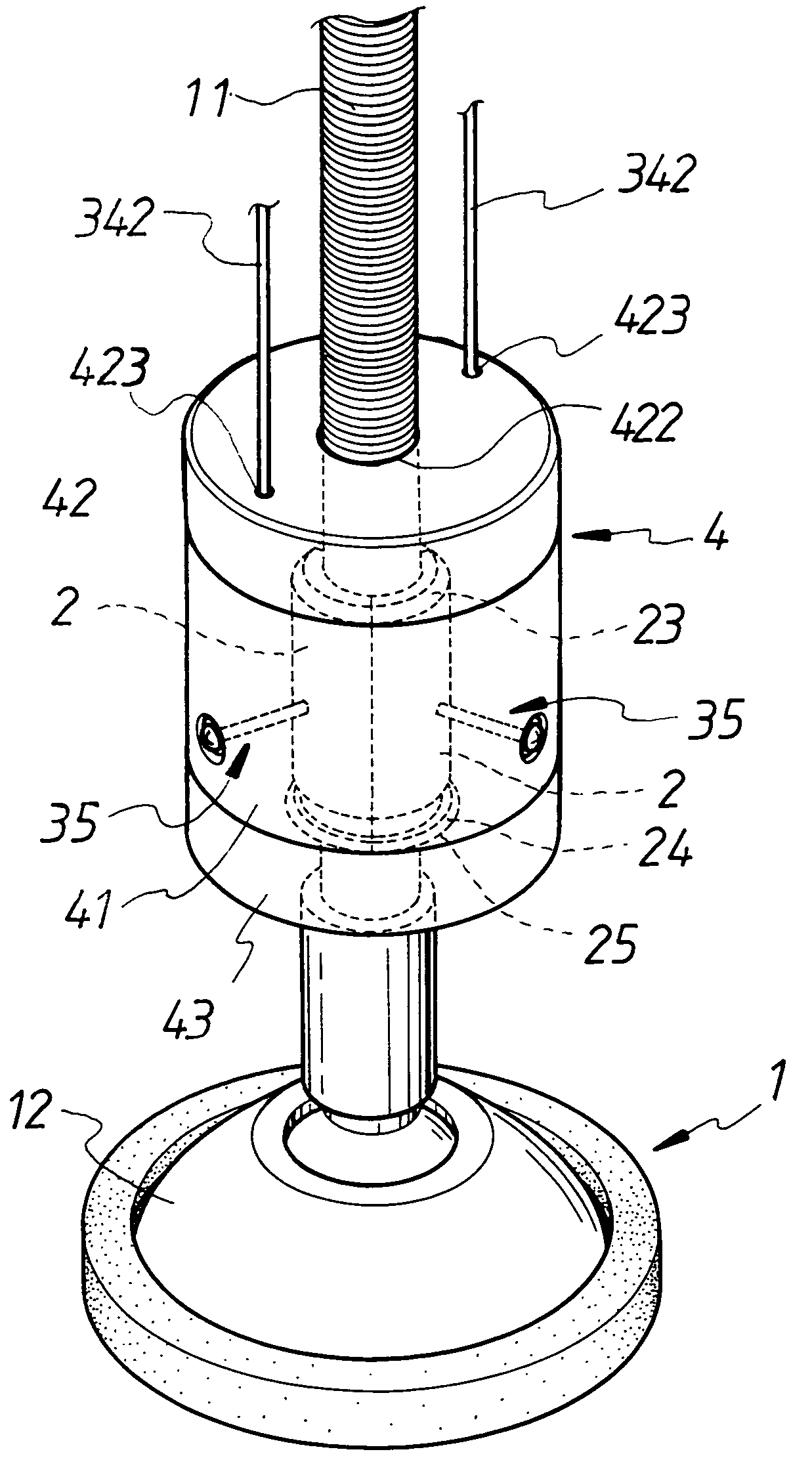
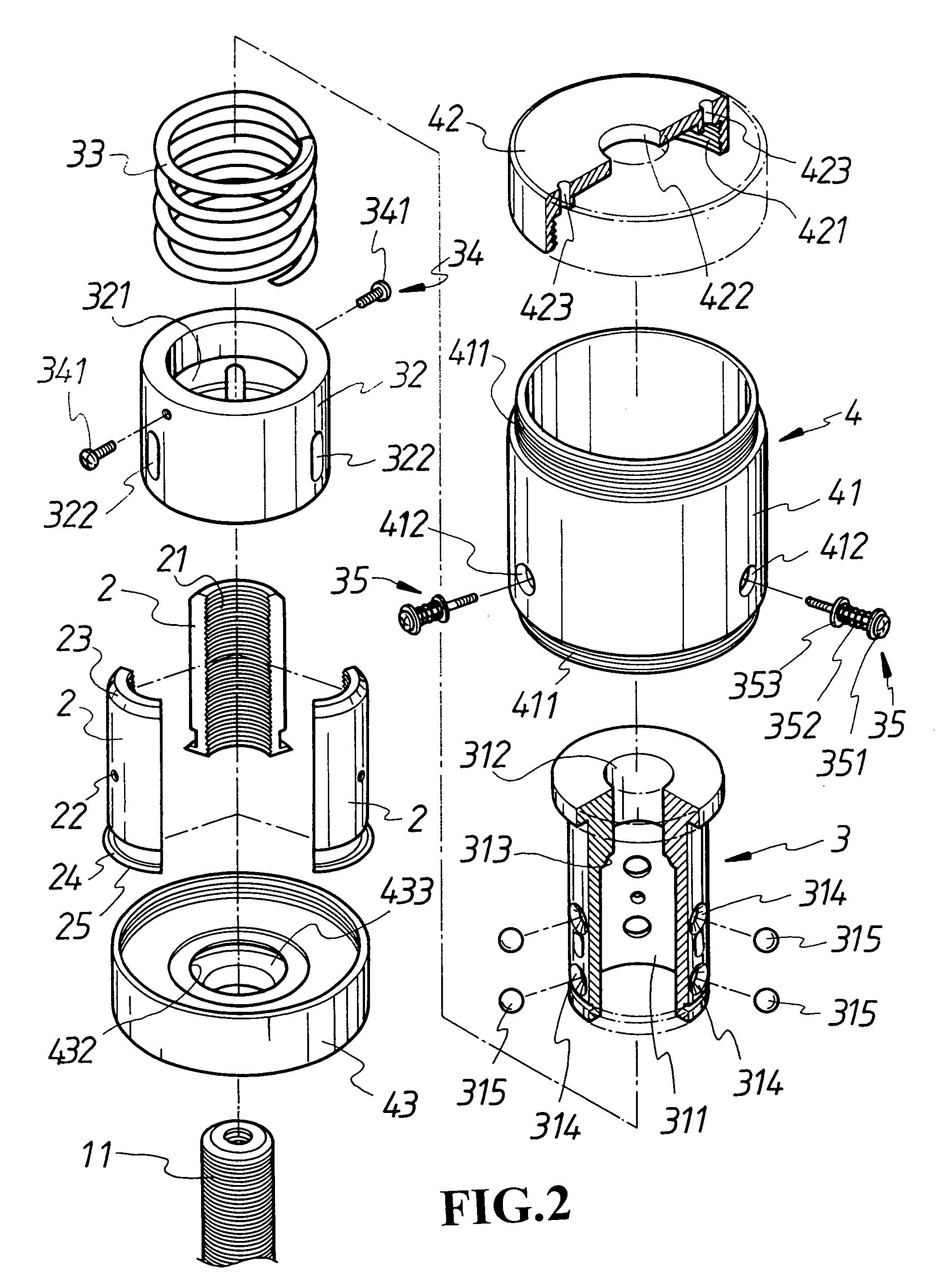
[0013]Referring to FIGS. 1 and 2, an adjustable support foot according to the present invention comprises a support post 1, a plurality of retaining plates 2, a control device 3 and an outer shell 4.

[0014]As shown in FIG. 1, the upper portion of the support post 1 is provided with a screwed axle 11, and the lower portion of the support post 1 is provided with a cup base 12. The axis of the cup base 12 can be fixed or of cardan shaft.

[0015]As shown in FIG. 2, the retaining plates 2 are elongated plates arced in the transverse direction. The inner wall of each of the retaining plates 2 is provided with a screw thread 21 capable of being engaged with the screwed axle 11. The outer wall of each of the retaining plates 2 is provided with at least one screw hole 22. A tapered surface 23 is formed on a lateral side of the outer wall of each of the retaining plates. The lower rim of each of the retaining plates 2 is provided with a flange 25 having a tapered surface 24, by which the screw t...


PUM


Abstract

An adjustable support foot comprises a support post, a plurality of retaining plates, a control device and an outer shell. The support post has a base and a screwed axle erected thereon. The retaining plates each provided with a screw thread cover around the screwed axle and are further enclosed by the control device including a retaining cylinder and a control ring. The control device urges the retaining plates to engage the screwed axle or depart from the screwed axle, by which the relative position of the support post in the outer shell can be quickly or mildly changed.

Description

BACKGROUND OF THE INVENTION[0001](a) Field of the Invention[0002]The present invention relates to adjustable support foots, and more particularly to an adjustable support foot mounted beneath a stepladder, a frame structure, a piece of furniture or a machine so that the height thereof can be adjusted to maintain stability.[0003](b) Description of the Prior Art[0004]The purpose of an adjustable support foot of the prior art mounted under a stepladder, a frame structure, a piece of furniture or a machine is for maintaining balance of the object thereon. It mainly includes a support pad and a bolt device above the foot. The bottom of an object, a stepladder, a frame structure, a piece of furniture or a machine, is provided with a plurality of adjustable support foots which are secured within corresponding screw holes thereon. To adjust the height of the support foots, some of the support pads have to be rotated, which is rather time consuming. For a user who needs to shift a stepladder...

Claims


Application Information

Patent Timeline
Patent Type & Authority Patents(United States)
IPC IPC(8): F16M7/00E06C7/44
CPCF16M7/00E06C7/44
Inventor HUANG, SHIH-YI
Owner HUANG SHIH YI
Why Eureka
Try Eureka