
Ball-point pen

a ball-point pen and pen body technology, applied in the field of ball-point pen, can solve the problems of easy wedge, inability to rotate or pull out the ball-point pen tip to replace refills, and inability to adjust the rotation speed of the ball-point pen tip, etc., to achieve convenient laser patterning, easy handheld, and easy replacement of refills

Inactive Publication Date: 2005-06-07
DONG GUAN SZU MAO STATIONERY GIFTS
View PDF4 Cites 17 Cited by
  • Summary
  • Abstract
  • Description
  • Claims
  • Application Information

AI Technical Summary

Benefits of technology

[0006]Accordingly, the first object of present invention is to provide a ball-point pen for conveniently replacing refills.
[0007]The second object of present invention is to provide a ball-point pen with unique and good looks.

Problems solved by technology

Among the methods, rotating to open or pulling out a ball-point pen tip to replace refills requires strenuous effort.
Therefore, high-quality pens rarely adopt this way to replace refills.
Also, rotating to open an upper tube to replace refills is time-consuming; pulling out an upper tube to replace refills may lead to the situation that an upper tube is improperly connected to a mid tube with seams and easily being wedged.
The conventional way to replace refills mentioned above is time-consuming and indirectly.
On the one hand, the cross section of existing ball-points is usually present as spherical-shaped, and such unitary look cannot meet people's demand for pretty individualized things.
On the other hand, less contact area between fingers and the pen may make people get tired easily during writing.

Method used


Image

  • Ball-point pen
  • Ball-point pen
  • Ball-point pen

Examples


Embodiment Construction

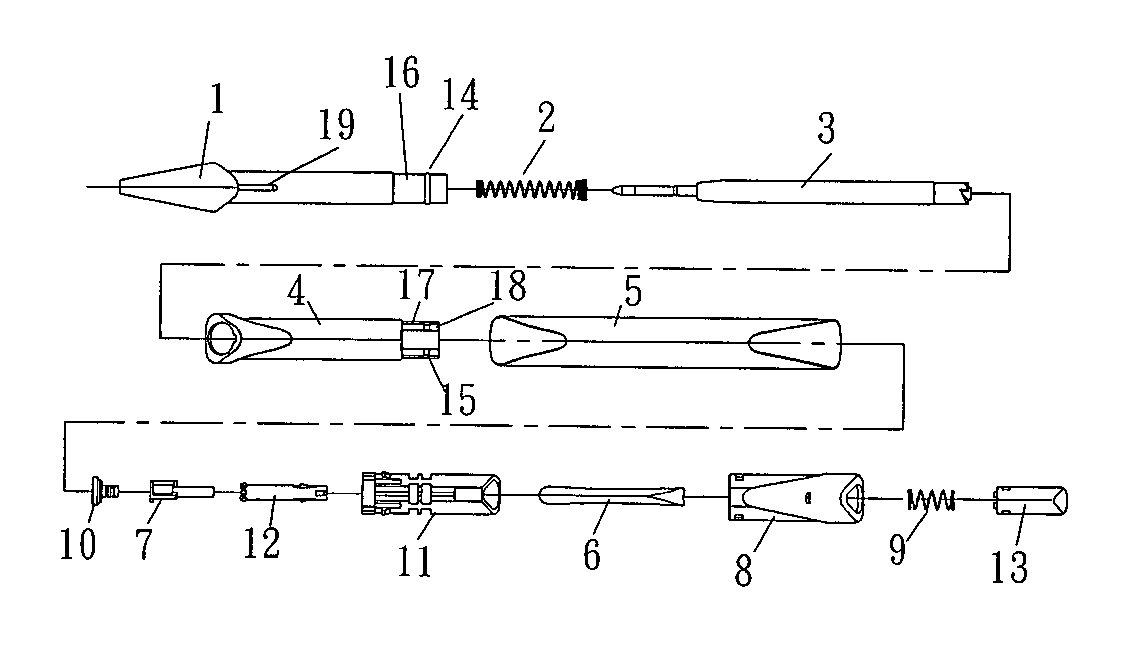
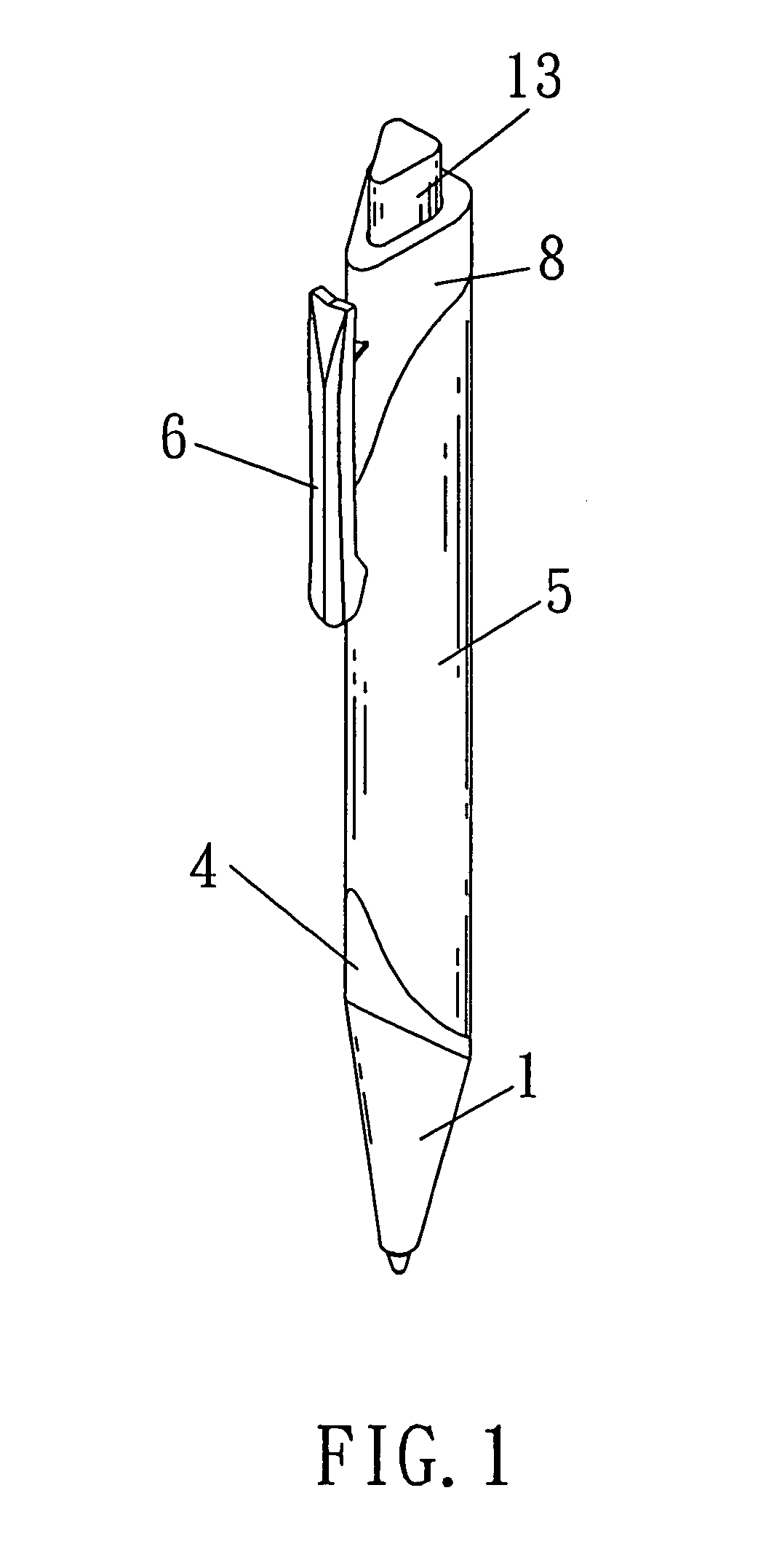
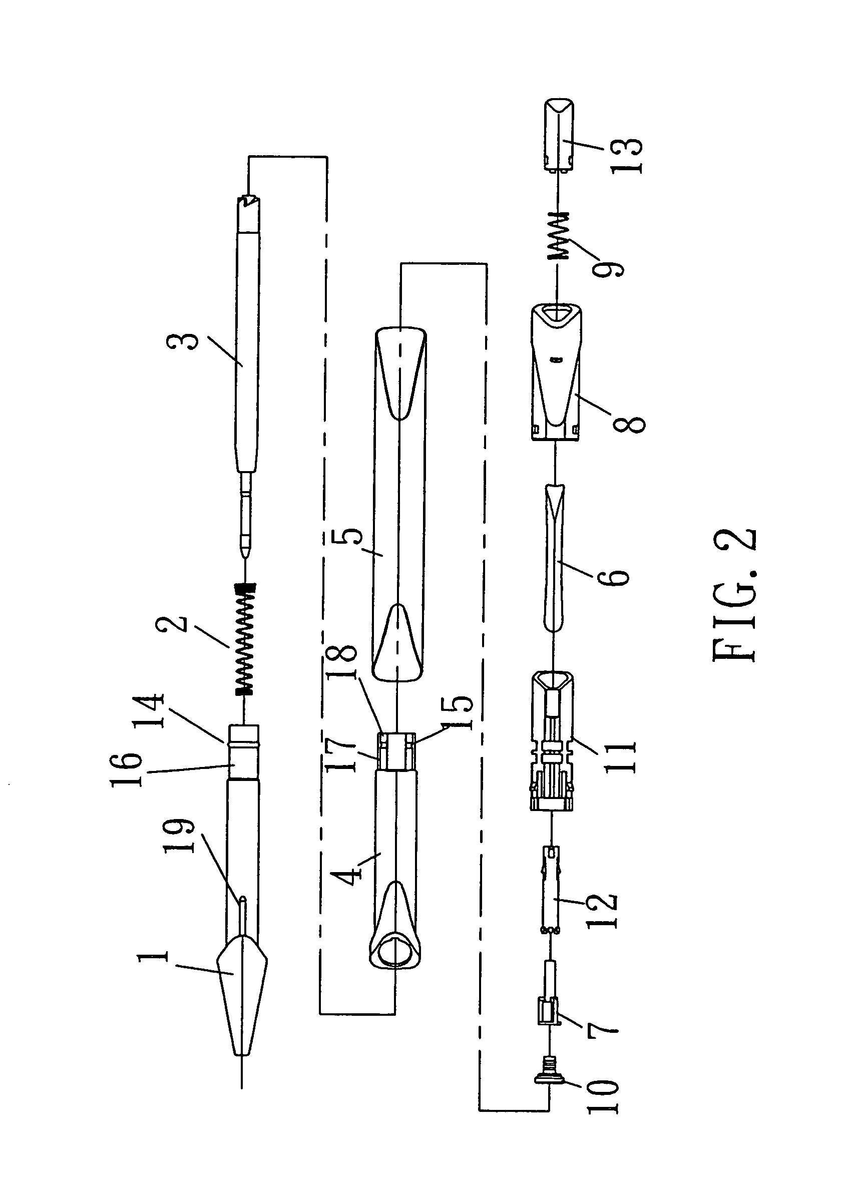
[0023]As shown in FIGS. 1, 2, and 3, the ball-point pen of the present invention includes a tip holder 1, a coil spring 2, a refill 3, a mid tube 4, an upper tube 5, a clip 6, a push bar 10, a sliding bar 7, a lower holder 11, a pen cap 8, a back plug spring 9, a sliding base 12, and a back plug 13, wherein an active back plug and push mechanism is composed of the push bar 10, sliding bar 7, sliding base 12, lower holder 11, back plug spring 9, and back plug 13; coil spring 2 is provided inside said tip holder 1; refill 3 is disposed inside the space formed between tip holder 1 and the body tube; lower holder 11 is fixed on said pen cap 8; sliding base 12, back plug spring 9, and back plug are slidably fixed inside lower holder 11; push bar 10 is fixed inside said sliding bar 7; and sliding bar 7 is placed inside sliding base 12. Also, a concave first stepped portion 16 is formed on the outer surface of the tip holder 1 in contact with one end of said body tube, and a protruded firs...


PUM


Abstract

A ball-point pen comprises: a ball-point pen tip, a coil spring, a refill, a mid tube, a upper tube, a clip, a sliding bar, a lower holder, a pen cap, a back plug spring, a sliding bracket, and a back plug; wherein the refill spring is placed inside the ball-point pen tip holder, the refill is placed inside the space formed between the tip holder and the mid tube, the lower holder is fixed on the pen cap, the sliding base, back plug spring, and back plug is fixed on the lower holder whiling being moveable, the sliding bar is fixed inside the sliding bar, the sliding bar is placed inside the sliding base, the refill is connected to the mid-connected tube, the mid-connected tube is connected to the upper-connected tube, and the upper-connected tube is connected to the pen cap. Accordingly, the characteristic of convenient replacement of refills, comfortable writing, and good appearance with regard to a ball-point pen can be achieved.

Description

BACKGROUND OF THE INVENTION[0001]1. Field of the Invention[0002]The present invention relates to a ball-point pen, and more particularly to a triangle-shape ball-point pen which provides an easy and convenient way for replacing refills and has good looks.[0003]2. Description of the Prior Art[0004]A variety of writing materials are present in the market now. Currently, ball-point pens are usually designed to allow for rotating to open or pulling out an upper tube, or rotating to open a ball-point pen tip in order to replace refills. Among the methods, rotating to open or pulling out a ball-point pen tip to replace refills requires strenuous effort. Therefore, high-quality pens rarely adopt this way to replace refills. Also, rotating to open an upper tube to replace refills is time-consuming; pulling out an upper tube to replace refills may lead to the situation that an upper tube is improperly connected to a mid tube with seams and easily being wedged. The conventional way to replace...

Claims


Application Information

Patent Timeline
Patent Type & Authority Patents(United States)
IPC IPC(8): B43K7/12B43K7/00
CPCB43K7/12B43K7/005
Inventor KUNG, LIN WEI
Owner DONG GUAN SZU MAO STATIONERY GIFTS
Learn More