
Device for connecting two components

Inactive Publication Date: 2005-06-07
KOMET GROUP GMBH
View PDF10 Cites 7 Cited by
  • Summary
  • Abstract
  • Description
  • Claims
  • Application Information

AI Technical Summary

Benefits of technology

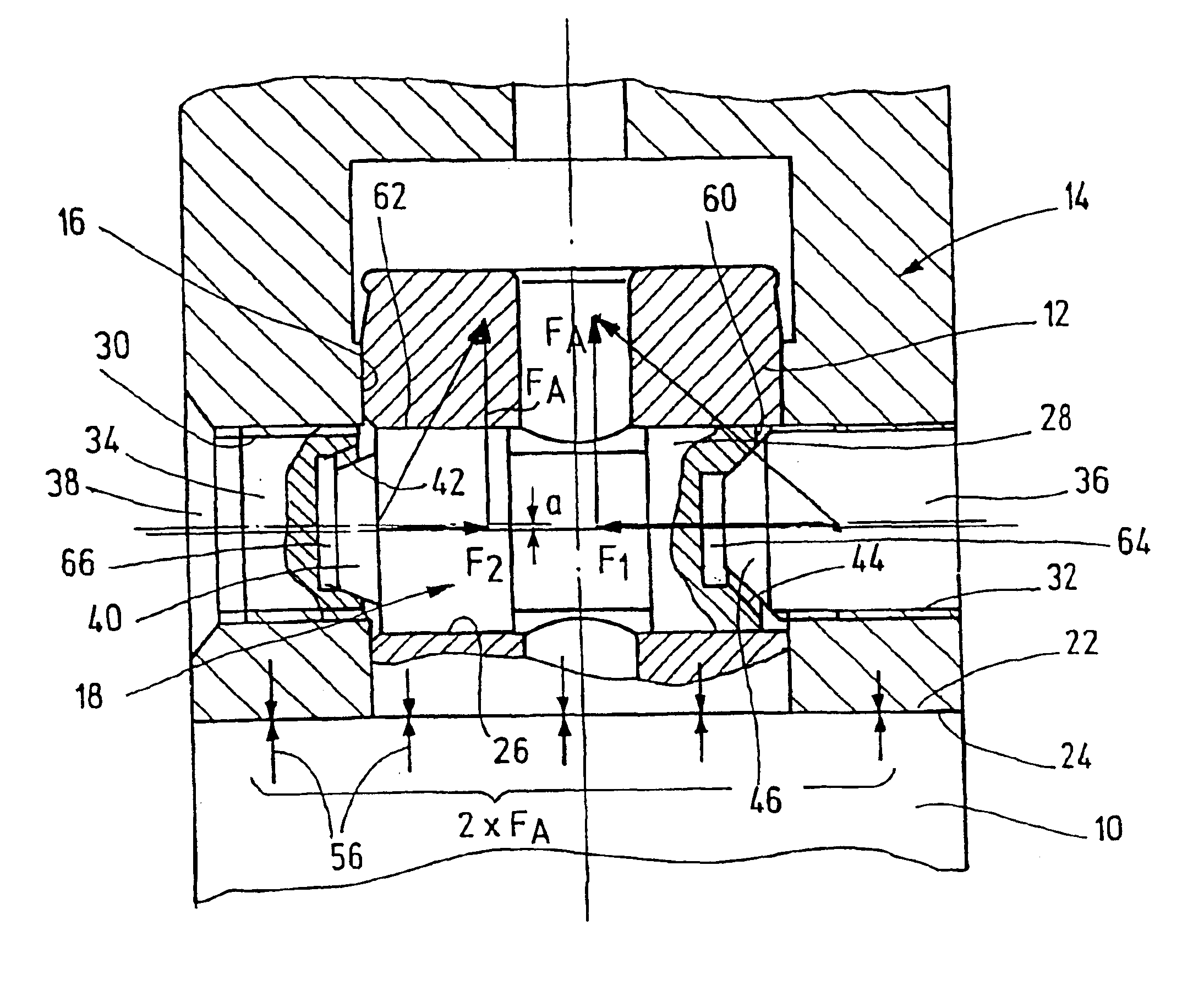
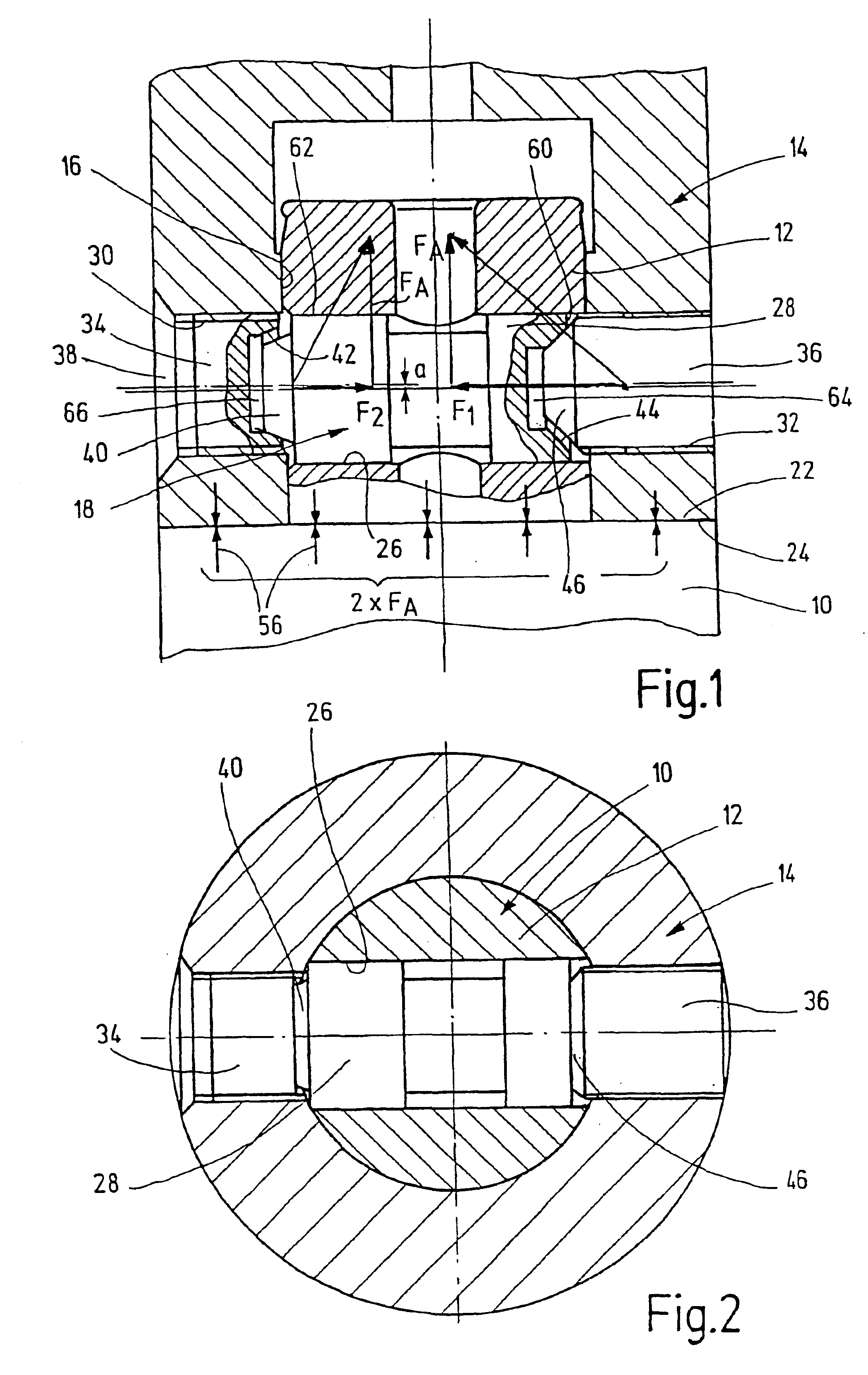
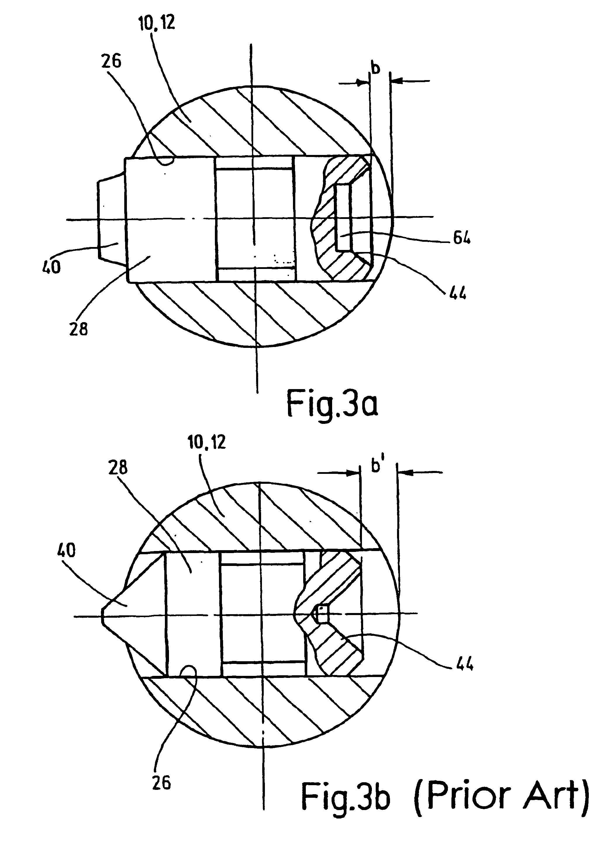
[0006]According to an alternative or advantageous embodiment of the invention, the clamp bolt has at least one frustum-shaped internal cone, the base diameter of which is at least 65%, advantageously 70 to 90%, of the guide diameter. In addition, it is advantageous when the height of the frustum-shaped internal cone is at a maximum 30%, preferably 10 to 25%, of the guide diameter.
[0012]It is achieved with the above measures that the guide surface, with which the clamp bolt rests frictionally against the inner surface of the transverse bore, can be optimized in its length. In this manner the friction forces to be overcome are minimized and the surface bearing pressure is improved in the area of the annular surfaces, viewed over the circumference.
[0014]The internal cones end advantageously on the frustum side in an enlarged bore. It is possible with this measure to utilize during the tensioning operation the full height of the internal cone without any danger of jamming.
[0015]In order to additionally improve the friction relationships in the threads, it is suggested according to a further preferred or alternative embodiment of the invention that at least one of the internal threads in the second component is followed toward the fitting bore by a threadless guide and support portion for the respective retainer designed as a screw. With this a precise guiding and supporting of the respective screw is guaranteed mainly in the area of the internal and external cones engaging one another in pairs. Furthermore, the guide length of the respective screw can be enlarged with this, with the result that the tendency for the screw to tilt and thus the friction is reduced, with the result that even when using a normal thread higher torques can be transferred into a planar surface tensioning.
[0016]A further preferred or alternative embodiment of the invention provides that one of the retainers is designed as a head bolt, which has an internal or external cone on its head side, and which can be inserted from the inside of the fitting bore into the associated radial bore. This measure achieves besides a secure seat of the retainer an improved force transfer at the transition points of the tensioning elements without the danger of swaging of material. It is particularly advantageous in this connection when the head bolt is inserted with its shaft, which is designed thread free, and / or with its head part into the radial bore in a press fit, which radial bore is preferably designed as a stepped bore. However, it is basically here also possible that the clamp bolt with its shaft carrying an external thread is screwed into the radial bore designed as a taphole. It is thereby important that the head bolt with its at least partly cylindrical and / or conical head part is force-lockingly supported on a wall portion of the radial bore, which wall portion is formed complementarily to the head part.

Problems solved by technology

Thus the longer the guide, the less is it possible for the clamp bolt to tilt and the smaller are the friction forces to be overcome.

Method used


Image

  • Device for connecting two components
  • Device for connecting two components
  • Device for connecting two components

Examples


Embodiment Construction

[0022]The connecting devices illustrated in the drawings are used to releasably couple components. “Components” are above and hereinafter understood to be primarily tool components, which house either a dowel or a fitting bore, thus in particular tool heads, tool shafts, adapter parts or intermediate elements, such as extension and reducing components, adjusting heads, spindle-adapter flanges and, if necessary, a tool spindle.

[0023]The connecting device consists essentially of a fitting plug 12 projecting axially beyond a first component 10, a fitting bore 16 arranged in a second component 14, and a tensioning mechanism 18 to pull the fitting plug 12 into the fitting bore 16 and to create a planar surface tensioning between an annular surface 22 on the first component 10, which annular surface 22 surrounds the fitting plug 12, and an annular surface 24 on the second component 14, in which annular surface is provided the fitting bore 16.

[0024]The tensioning mechanism 18 houses a clam...


PUM

PropertyMeasurementUnit
Fractionaaaaaaaaaa
Fractionaaaaaaaaaa
Fractionaaaaaaaaaa

Abstract

The tensioning mechanism (18) comprises a clamp bolt (28), arranged in a displaceable manner in a transverse bore (26) in the fitting plug (12) and two diametrically opposed retainers (34, 36) in the second component (14) which engage with an axially facing internal or external cone against a complementary internal or external cone on the clamp bolt (28) and, during tensioning, are tensioned with the same in a wedge fashion. According to the invention, the clamp bolt (28) comprises a frustum-shaped external cone (40), the base diameter of which is smaller than the diameter of the guide surface (62) thereof in the transverse bore (26).

Description

BACKGROUND OF THE INVENTION[0001]The invention relates to a device for connecting two components, in particular two tool parts, comprising a cylindrical fitting plug arranged on the first component, and comprising a radially projecting annular surface surrounding the fitting plug at its root, comprising a cylindrical fitting bore arranged in the second component for receiving the fitting plug, and comprising an annular surface surrounding the fitting bore at its edge, comprising a clamp bolt, which is movably guided with a cylindrical guide surface in a transverse bore in the fitting plug, and has on its axially facing ends an internal or external cone concentric with respect to said guide surface, and the length of which clamp bolt is smaller than the diameter of the fitting plug in the area of the transverse bore, and comprising two retainers, which are inserted into radial bores, which are diametrically opposed in the area of the fitting bore and are preferably provided with an i...

Claims


Application Information

Patent Timeline
IPC IPC(8): B23B31/10B23B31/107
CPCB23B31/1077Y10T408/95Y10T403/7064Y10T403/7041Y10T403/7067Y10T403/7015Y10T408/94Y10T279/17821Y10T403/7066
Inventor STOLZ, GERHARDSTAHL, FRANK
Owner KOMET GROUP GMBH
Learn More