Hinged and latched raceway

Active Publication Date: 2005-06-07
PANDUIT
View PDF16 Cites 74 Cited by
  • Summary
  • Abstract
  • Description
  • Claims
  • Application Information

AI Technical Summary

Benefits of technology

[0003]The present invention is directed to a hinged duct system having a base member and a cover. The base member has a bottom wall, a first sidewall and a second sidewall. The base member also includes a channel located between the sidewalls. The cover has a top wall, a first end portion and a second end portion. The cover is hingedly attached to one of the sidewalls of the

Problems solved by technology

Removal, storage and replacement of the cover over the entire system during this process can be time consuming and otherwise problematic.
However, certain duct c

Method used


Image

  • Hinged and latched raceway
  • Hinged and latched raceway
  • Hinged and latched raceway

Examples


Embodiment Construction

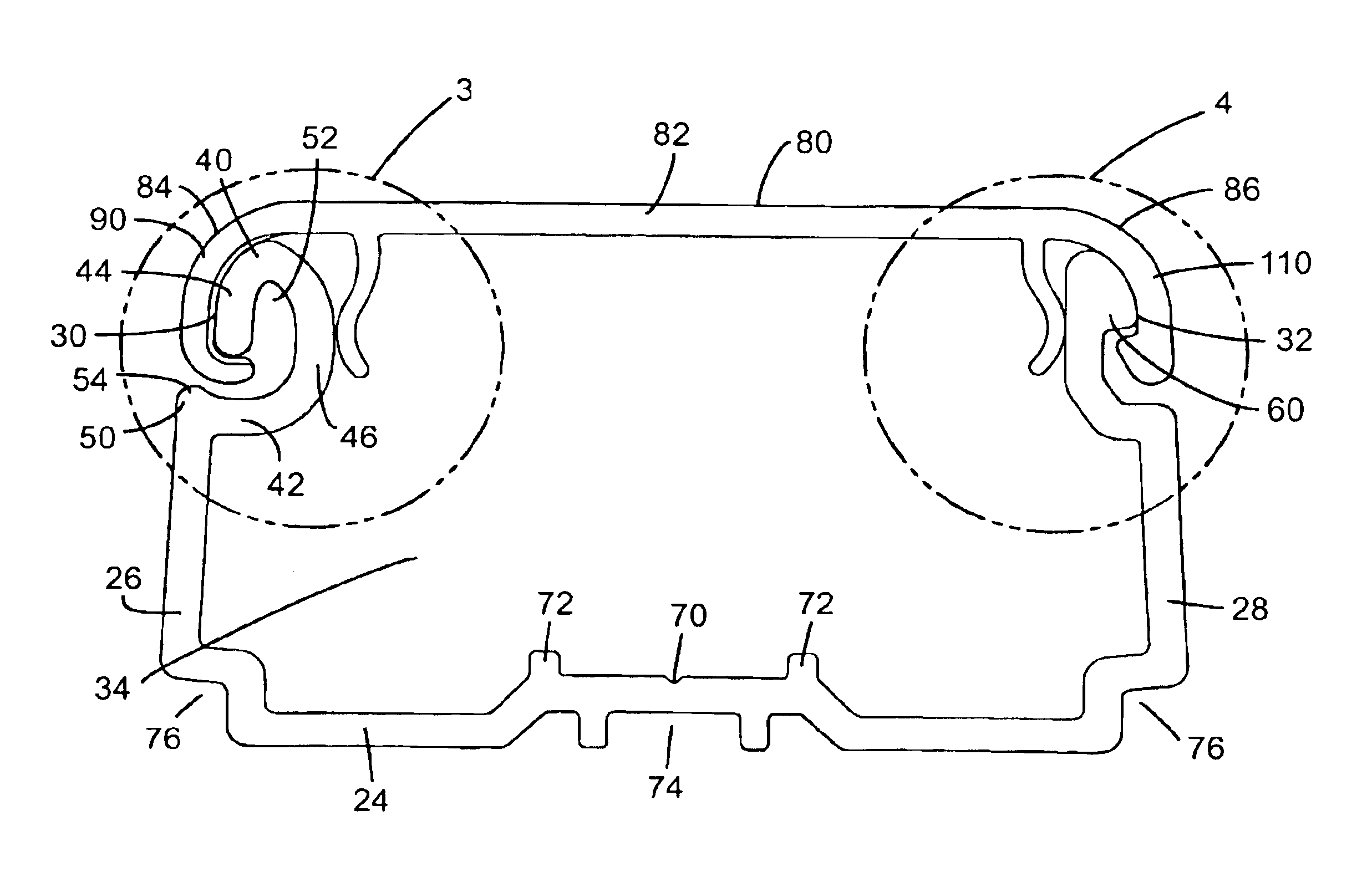
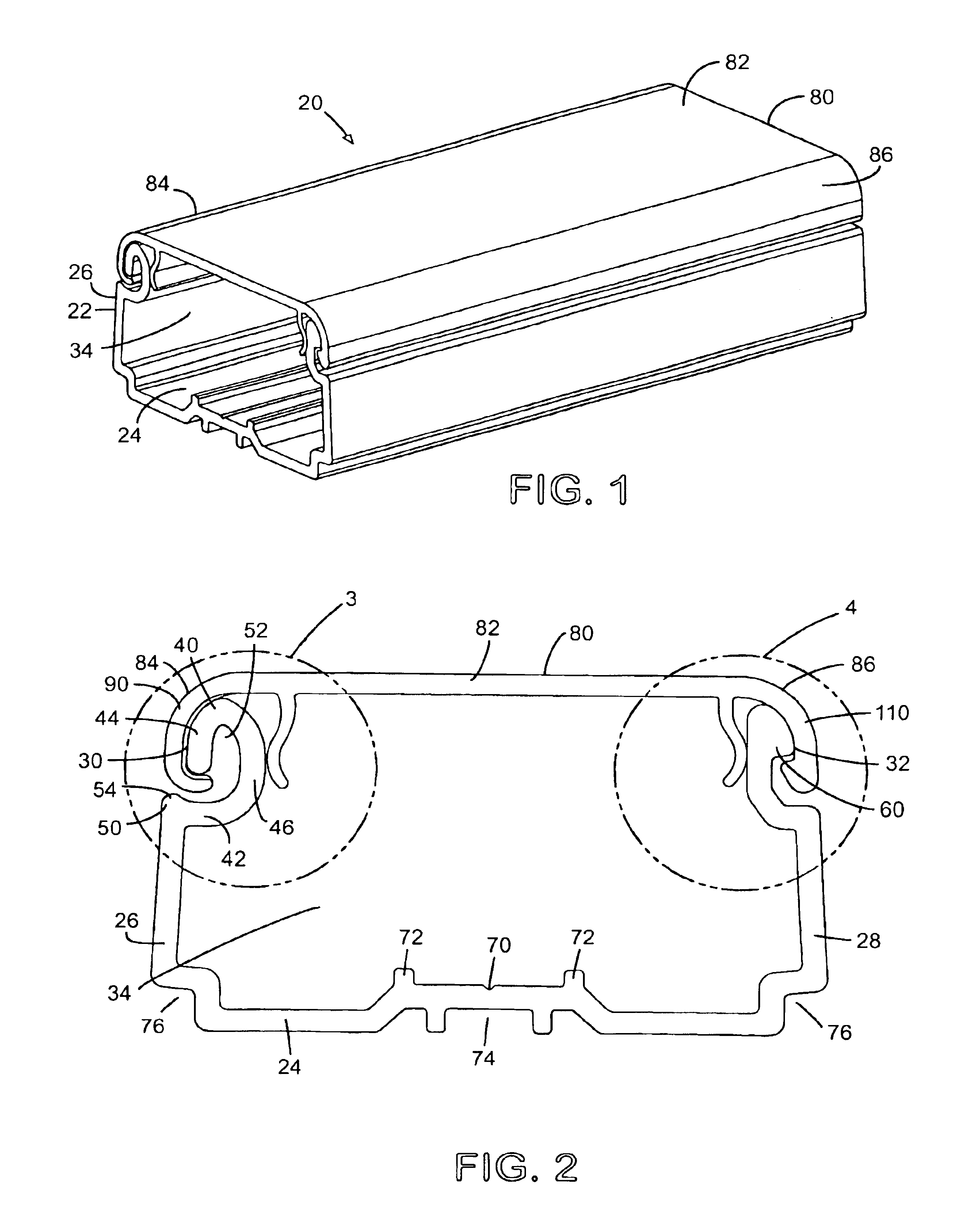
[0021]One embodiment of the hinged and latched raceway or duct 20 of the present invention is illustrated in FIGS. 1-9. A second embodiment of the hinged and latch raceway is illustrated in FIGS. 10-15. As illustrated in FIGS. 1 and 10, each embodiment of the raceway includes a base 22 and a cover 80 that is secured to the base 22 by a hinge mechanism on one side and a latch mechanism on the opposite side. The raceway may be formed from any suitable material, but is preferably formed from a plastic material, such as PVC.

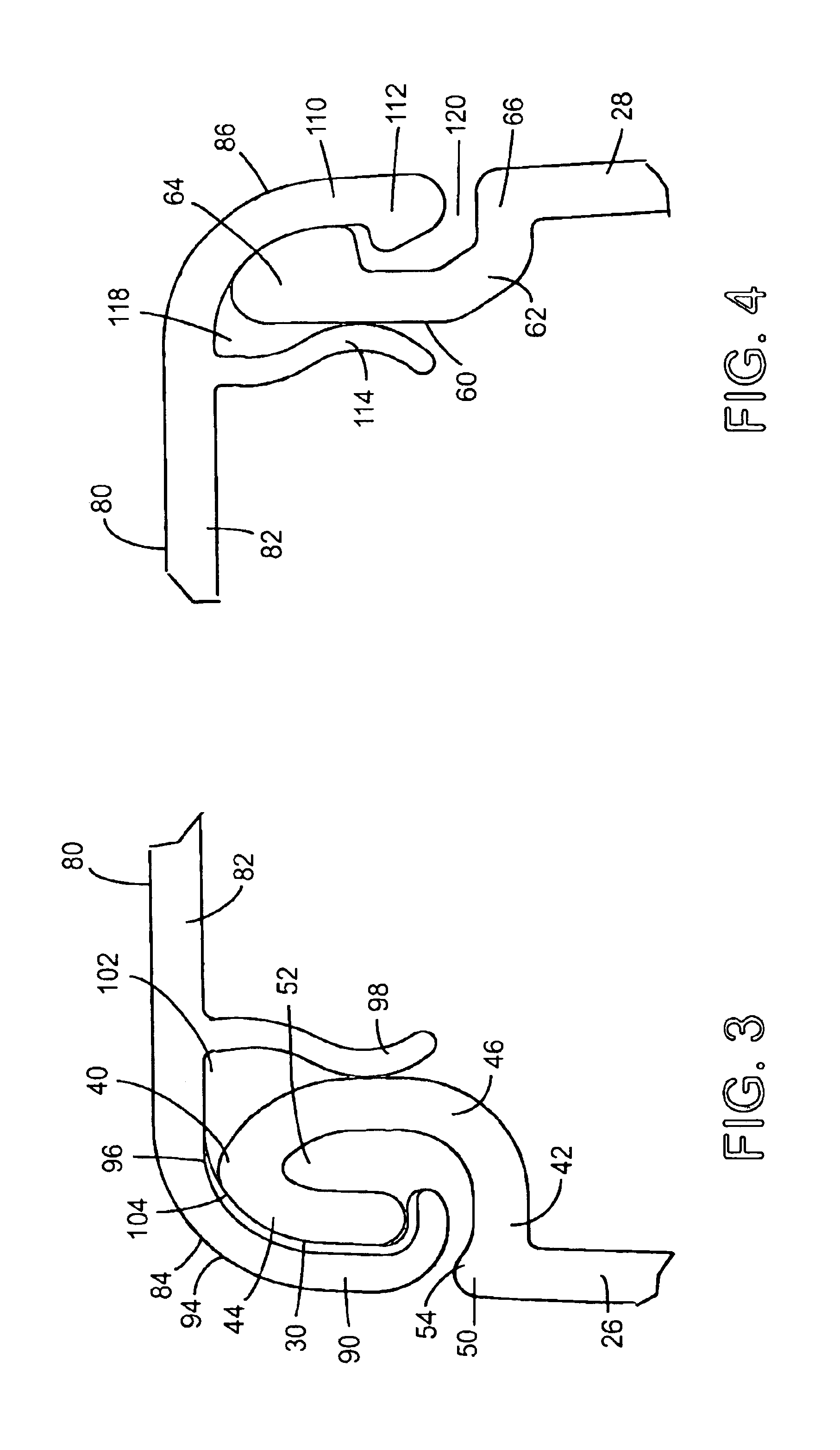
[0022]As shown in FIG. 2, the base 22 has a bottom wall 24 and first and second sidewalls 26, 28 which may be integrally formed or otherwise affixed together. The bottom wall 22 and the sidewalls 26, 28 define a receiving channel 34 for wires or the like. The distal end 30 of the first sidewall 26 includes a hook 40 that forms part of the hinge mechanism. The hook 40 includes a flange 42 that extends inwardly into the receiving channel 34 from an edge 50 of the sidew...


PUM


Abstract

A hinged duct system having a base and a cover hingedly attached to the base. The base has a bottom wall, a first sidewall and a second sidewall that define a channel therebetween. The cover has a top wall, a first end portion and a second end portion. The cover is attached to one of the sidewalls of the base by a hinge mechanism. The hinge mechanism has a hook member located at a distal end of one of the sidewalls of the base and a hook member located at one of the end portions of the cover. A flexible member is disposed along the hinge mechanism to preventing the cover from sliding with respect to the base when the cover rotates about the base.

Description

FIELD OF THE INVENTION[0001]The present invention relates to a wiring cable duct system including a base and a cover, and more particularly to a wiring cable duct system having a cover attached to the base by a hinge mechanism on one side to allow the cover to rotate for easy access in the raceway and a latch mechanism on the opposite side to secure the cover when in a closed position.BACKGROUND OF THE INVENTION[0002]A wide variety of wiring duct and raceway systems are known for routing various types of wires and cables. Typical duct or raceway systems consist of a base member and a cover that may be hinged, snap latched or otherwise engageable with the base. In operation, it often becomes necessary to remove or open the cover to allow access to the cable containing area of the base member. Frequently, an installer needs to repair, reconfigure or install new cables in the raceway system. Removal, storage and replacement of the cover over the entire system during this process can be...

Claims


Application Information

Patent Timeline
IPC IPC(8): H02G3/04
CPCH02G3/0418
Inventor VANDERVELDE, CHARLESWOODS, RANDALL T.ROULEAU, RODNEY G.
Owner PANDUIT
Why Eureka
Try Eureka