Transition duct support bracket wear cover

a technology of duct support brackets and wear covers, which is applied in the direction of machines/engines, stators, engine components, etc., can solve the problems of high manufacturing cost, premature repair or replacement of support brackets, and complex assembly of manufacturing parts, and achieves cost-effective manufacturing, reduced manufacturing time, and easy formation

Inactive Publication Date: 2005-06-14
ANSALDO ENERGIA SWITZERLAND AG
View PDF3 Cites 28 Cited by
  • Summary
  • Abstract
  • Description
  • Claims
  • Application Information

AI Technical Summary

Benefits of technology

[0008]The present invention seeks to overcome the shortfalls of the prior art by providing a wear cover for a transition duct support bracket that provides wear protection on all critical surfaces of the support bracket fingers while having a configuration that is more cost efficient to manufacture. The wear cover disclosed in the present invention contains a first and second leg portions, substantially parallel to each other, and a third leg portion generally perpendicular to the first and second leg portions. The leg portions are interconnected by two regions of curvature, which together form the wear cover. The wear cover is manufactured from a single sheet of material that is easily formed to the desired geometry and does not require any assembly or welding, thereby significantly reducing the manufacturing time. Furthermore, due to the improved design and simpler manufacturing techniques, component cost is reduced by more than 50%, with the majority of the remaining cost due to the sheet metal not manufacturing. The wear cover easily slides over each finger of a support bracket and is then fixed to the finger to protect its surfaces that are in contact with a transition duct mounting block. Each of the wear cover leg portions have a width extending a distance such that the support bracket finger is protected over the entire contact surface with a mounting block.
[0009]It is an object of the present invention to provide a wear cover for a transition duct support bracket that has reduced manufacturing complexity and can be produced at a lower cost.

Problems solved by technology

Due to the vibrations experienced by the combustion system and adjacent transition duct, frictional contact at the interface region between a support bracket and transition duct has been known to create excessive wear, especially on the support bracket, resulting in premature repair or replacement of the support bracket.
While the sleeve tends to reduce wear to the support bracket fingers, it is a complex assembly with respect to manufacturing.
As a result of this extensive manufacturing process, the cost of this sleeve design is expensive, often as much as 25%-35% of the support bracket cost.
Furthermore, as with the first sleeve embodiment, the second embodiment also requires complex manufacturing techniques to prepare a sleeve in a flat pattern, then form it into the final shape as shown in FIG.

Method used


Image

  • Transition duct support bracket wear cover
  • Transition duct support bracket wear cover
  • Transition duct support bracket wear cover

Examples


Embodiment Construction

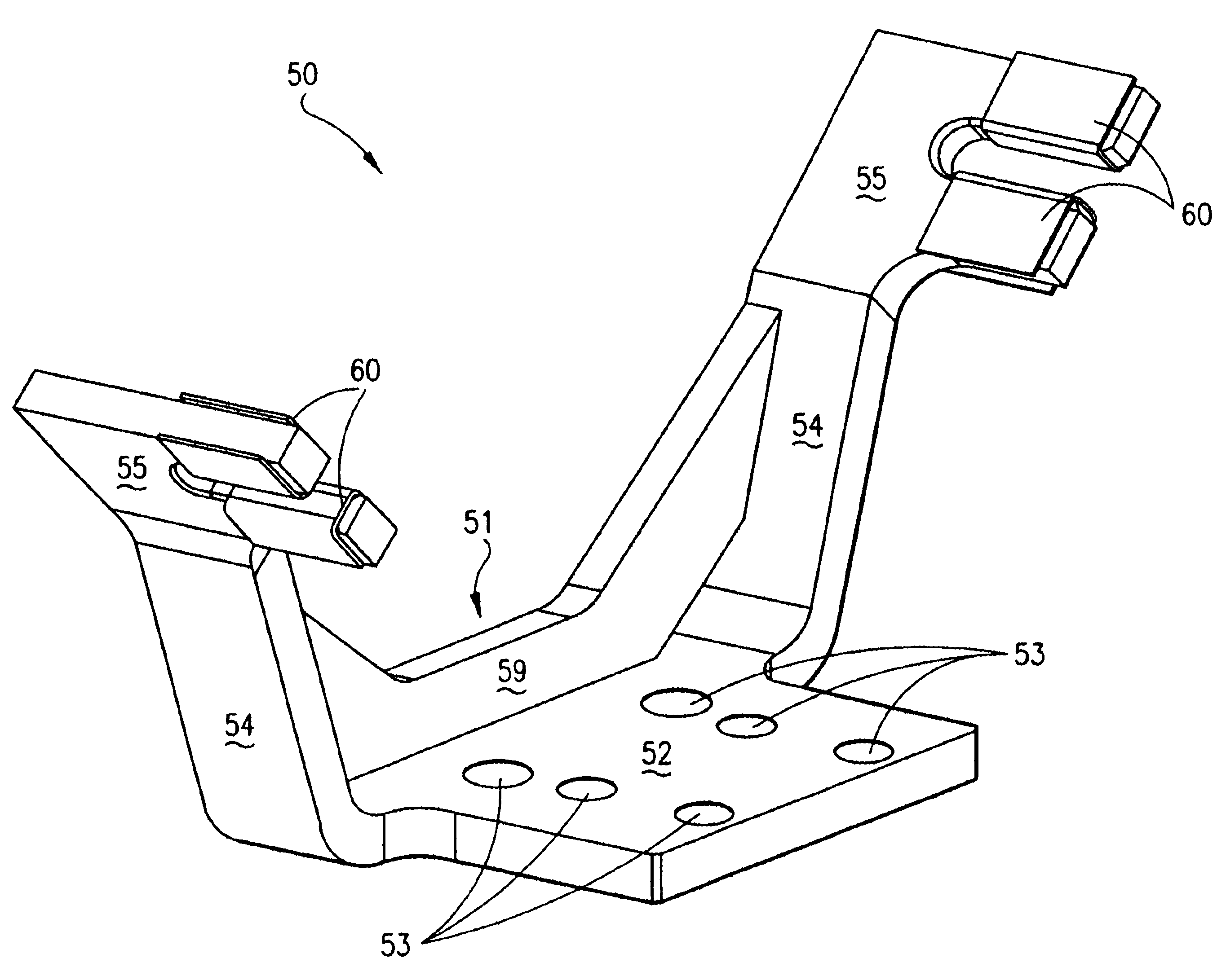
[0022]The present invention is shown in detail in FIGS. 6-9, with a support bracket assembly 50 shown in perspective view in FIG. 6. Bracket assembly 50 includes a support bracket 51 having a mounting plate 52, which contains a plurality of holes 53 for securing support bracket assembly 50 to a gas turbine engine. Support bracket 51 also contains a plurality of support arms 54 that extend outward from mounting plate 52, with each support arm 54 having at least one finger 55 for engagement with a transition duct. Referring briefly to FIGS. 8 and 9, at least one finger 55 also has a first thickness 56, typically at least 0.250 inches, a first length 57, and a first width 58. In the preferred embodiment of the present invention, support bracket 51 contains four fingers 55, such that two fingers extend from each support arm 54. Referring back to FIG. 6, support bracket 51 also contains a reinforcement plate 59 that is generally perpendicular to mounting plate 52 and is fixed to both mou...


PUM


Abstract

A wear cover for use on a gas turbine transition duct support bracket is disclosed. The wear cover, which is manufactured from a single piece of sheet metal, does not require complex manufacturing processes or tools, thereby reducing component cost. The wear cover comprises first and second leg portions substantially parallel to each other and each generally perpendicular to a third leg portion. Each of the leg portions serve to protect a surface of a support bracket finger from excessive wear associated with frictional contact with mounting blocks of a transition duct. The wear cover is designed to slip onto a support bracket finger through a first opening and is fixed to the finger by a means such as welding.

Description

BACKGROUND OF THE INVENTION[0001]1. Field of the Invention[0002]This invention relates to gas turbines in general, but more specifically to the interface region between a transition duct and a support bracket assembly.[0003]2. Description of Related Art[0004]In a typical land-based gas turbine engine, a plurality of combustors is positioned in a circular array about the engine such that each combustor delivers hot combustion gases to the turbine. The hot combustion gases are transferred to the turbine through a transition duct. The transition duct, at its inlet end is positioned adjacent the combustor exit by a support bracket. An example of a transition duct inlet and support bracket of the prior art is shown in FIG. 1. Due to the vibrations experienced by the combustion system and adjacent transition duct, frictional contact at the interface region between a support bracket and transition duct has been known to create excessive wear, especially on the support bracket, resulting in...

Claims


Application Information

Patent Timeline
Patent Type & Authority Patents(United States)
IPC IPC(8): F02C7/20
CPCF02C7/20F01D9/023
Inventor MACK, BRIAN R.
Owner ANSALDO ENERGIA SWITZERLAND AG
Why Eureka
Try Eureka