Structure of linear sliding rail circulating device

a technology of linear sliding rails and circulating devices, which is applied in the direction of linear bearings, shafts and bearings, bearings, etc., can solve the problems of reducing the manufacture benefit, reducing the precise size at the time of manufacture, and increasing the manufacture cost. , to achieve the effect of efficient and appropriate control of the gap issue, reducing manufacturing costs, and easy production

Inactive Publication Date: 2006-04-13
ABBA LINEAR TECH
View PDF9 Cites 19 Cited by
  • Summary
  • Abstract
  • Description
  • Claims
  • Application Information

AI Technical Summary

Benefits of technology

[0010] The primary object of the invention is to provide a linear sliding rail circulating device, which is applicable to various rails, changeable with end components, assembly-exchangeable with common fittings, and therefore efficiently reducing the manufacture costs.
[0011] Another object of the invention is to provide an end component structure, which can efficiently and appropriately control the issue in gap, be easily produced, and be efficient in manufacture cost and time.
[0012] To achieve the above objects, the invention is primarily composed of a rail, a sliding base, ends, a rolling element, a sustainer, an anti-dust cover, etc. Said ends can be freely assembled and are each composed of a middle end block, a left end block and a right end block, which can be engaged and combined with each one another before being fastened to the front and rear ends of the sliding base. Besides, said end blocks can have the cross-section in form of an H or a recessive U, in order to alter the pattern of the laterally corresponding sides in the aperture of the rail sliding path. As such, common fittings can be applicable to partial structure of various rails, thus ease maintenance and curtail manufacture costs.
[0013] Meanwhile, in view of the fact that the design of the chain of the rolling element presents a multi-angle saddle, and that the wings of the rolling element can have an arrangement of different vertical-central lines, the rolling element can be applicable to recessive U-type rail sliding device, thus reducing the manufacture costs.

Problems solved by technology

In view of this, in order to avoid inaccuracy in size for assembly, there exists difficulty in enhancing the precise size at the time of manufacture.
As shown in FIG. 2, the perfect design for a conventional linear sliding rail is that the ends 14 and rail 11 keep an appropriate gap distance a. However, if the gap distance a is too great, the rolling element 13 will easily detach due to the gap distance a, thus reducing the manufacture benefit.
However, as there exists problem in the gap between said rail 11 and sliding base 12, the manufacture costs would be considerably increased.

Method used


Image

  • Structure of linear sliding rail circulating device
  • Structure of linear sliding rail circulating device
  • Structure of linear sliding rail circulating device

Examples


Embodiment Construction

[0050] The following descriptions are of exemplary embodiments only, and are not intended to limit the scope, applicability or configuration of the invention in any way. Rather, the following description provides a convenient illustration for implementing exemplary embodiments of the invention. Various changes to the described embodiments may be made in the function and arrangement of the elements described without departing from the scope of the invention as set forth in the appended claims.

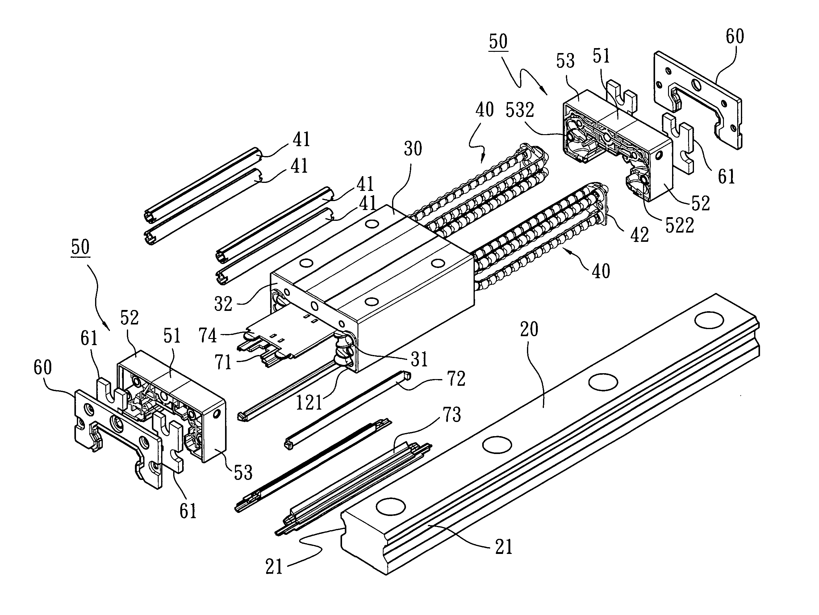
[0051] Referring to FIG. 6, the linear sliding rail circulating device is provided with a rail 20, a sliding base 30, two rolling elements 40, two ends 50 and two anti-dust covers 60.

[0052] The outline of the rail 20 appears as an H and is laterally formed with rails 21 at two sides, such that the sliding base 30 can slide along the rail 20. The sliding base 30 is provided with rolling elements 40 inside and apertures 31 at the interior walls for receiving the rolling elements 40, which theref...


PUM


Abstract

An improved structure of linear sliding rail circulating device is primarily composed of: a rail, which laterally forms a sliding path; a sliding base, which slides to operate along said rail, and is provided with an aperture at the interior for receiving the rolling elements; and combination ends, which are circulating system correspondingly formed subject to the H-shape or U-shape rail for connecting to the front and rear ends of the sliding base to serve as closes of the rolling path of the rolling elements and U turns for the rolling elements. Accordingly, rails of various types can be partially altered common components, thereby easing device maintenance and minimizing manufacture costs.

Description

BACKGROUND OF THE INVENTION [0001] (a) Technical Field of the Invention [0002] The present invention relates to a linear sliding rail circulating structure design, particularly to a sliding base, the components for the ends of which can be assembled by modules and altered to be applicable to extrusive or depressive rails, thereby having better resilience to ease manufacture of various type of linear sliding rail circulating devices. [0003] (b) Description of the Prior Art [0004] As shown in FIG. 1, a conventional linear sliding rail 10 structure is substantially composed of a rail 11 and a sliding base 12, which can slide along the rail 11. A groove is provided at the interior two sides of the sliding base 12 for receiving rolling balls (not shown), while the rear ends that the groove extends are sealed with ends 14, which are interiorly provided with an U-turn groove 121 for the rolling balls (not shown) to alter direction (also refer to FIG. 2). The outside of each end 14 is faste...

Claims


Application Information

Patent Timeline
Patent Type & Authority Applications(United States)
IPC IPC(8): F16C29/06
CPCF16C29/0607F16C29/0609F16C29/0611F16C29/063F16C29/0647F16C29/084F16C33/3825
Inventor LEE, MAO-TU
Owner ABBA LINEAR TECH
Why Eureka
Try Eureka