Display device

Inactive Publication Date: 2005-06-14
3M INNOVATIVE PROPERTIES CO
View PDF19 Cites 22 Cited by
  • Summary
  • Abstract
  • Description
  • Claims
  • Application Information

AI Technical Summary

Benefits of technology

[0009]The present invention comprises a display device having controlled illumination and viewing. In one embodiment a display element is combined with first and second light control elements. The first and second light control elements cooperatively limit the directionality of light from a light source illuminating the display element in at least two directions. Only one of the first and second light control elements limits the directionality of reflected ambient light illuminating the display.

Problems solved by technology

Only one of the first and second light control elements limits the directionality of reflected ambient light illuminating the display.

Method used


Image

  • Display device
  • Display device
  • Display device

Examples


Embodiment Construction

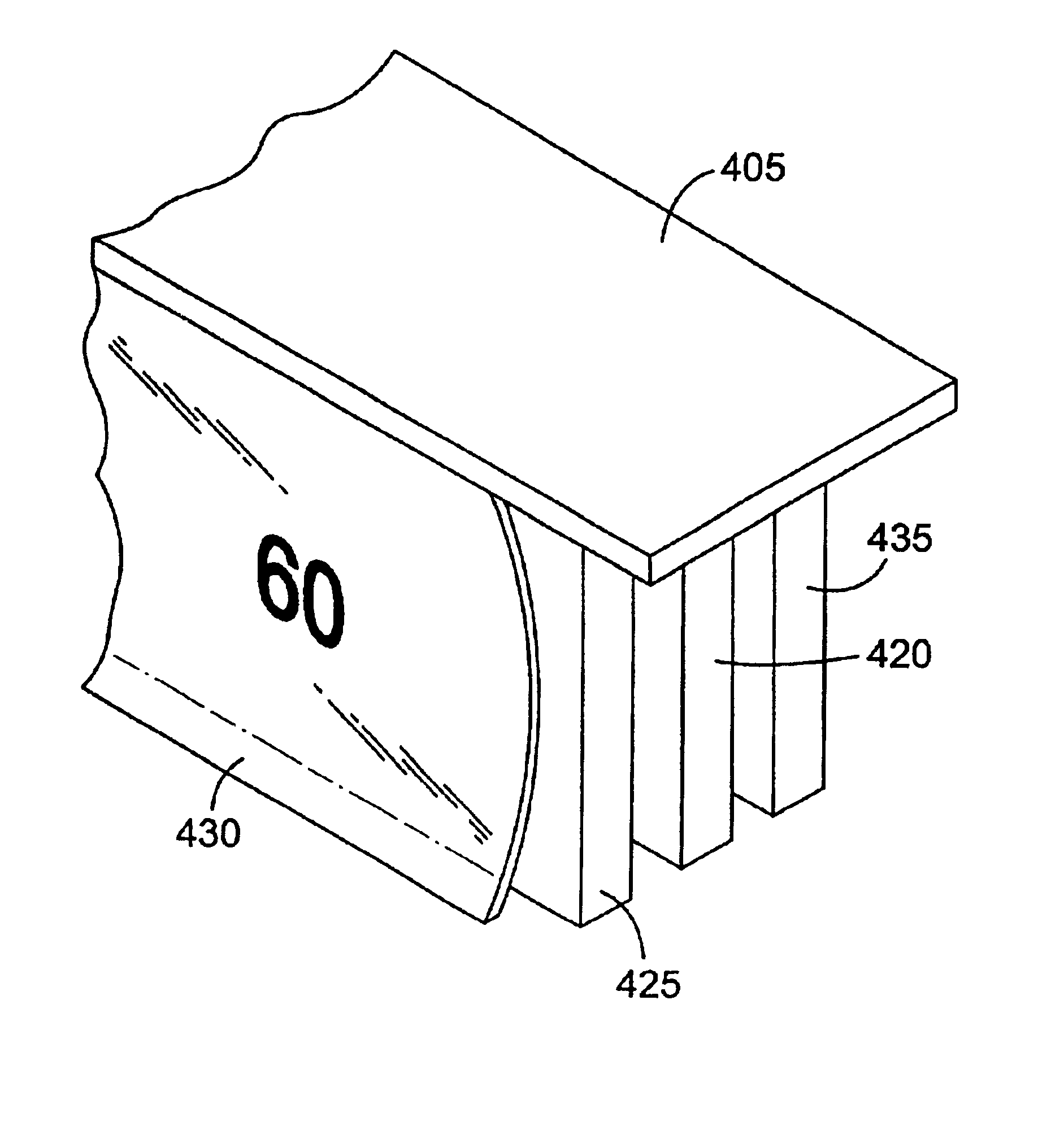
[0018]Where used herein, unless noted otherwise, the terms “in front of” and “forward” refer to relative positions proximal to or within the display or instrument panel which are toward the viewer, and the terms “behind” and “rearward” refer to relative positions proximal to or within the display or instrument panel which are away from the viewer.

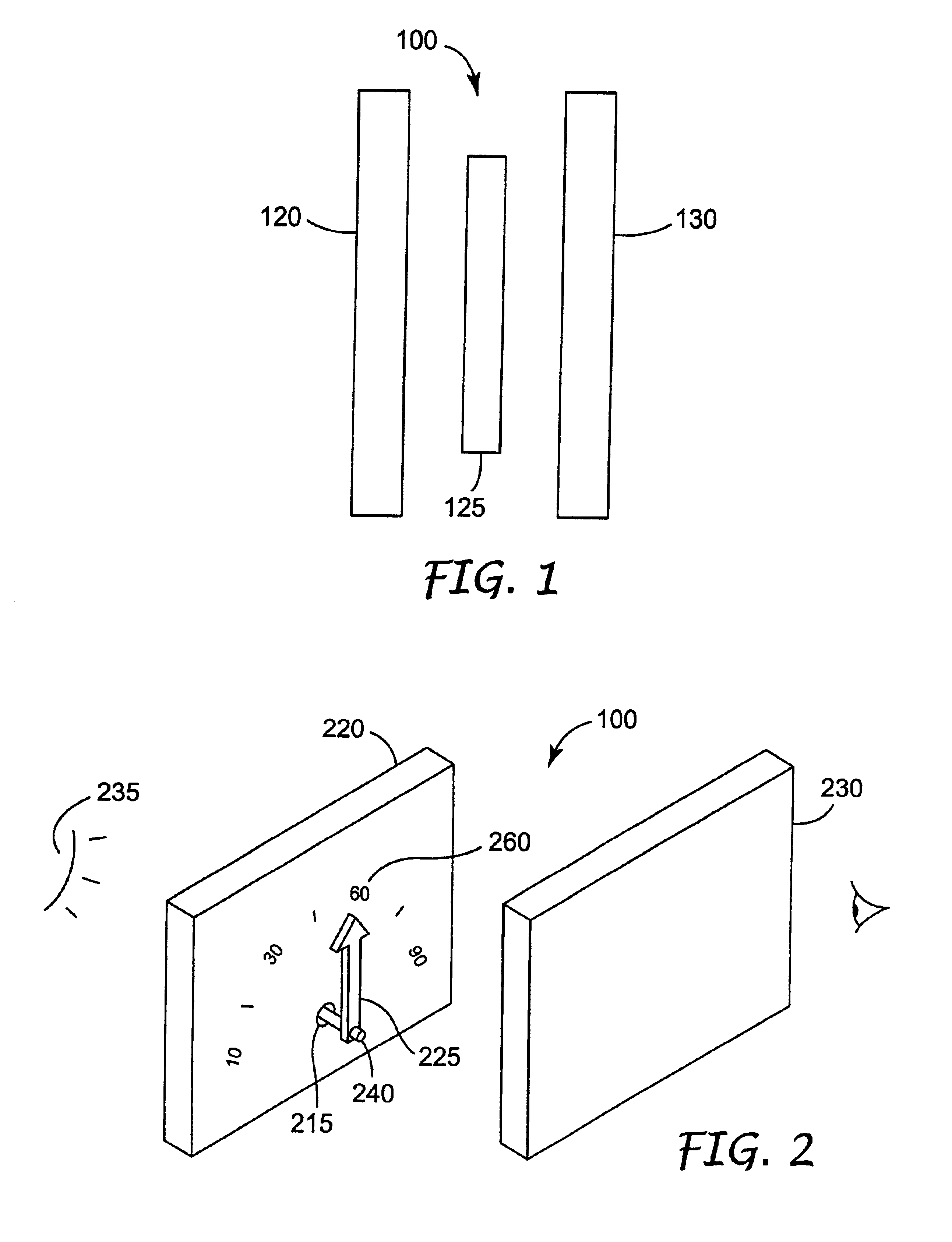
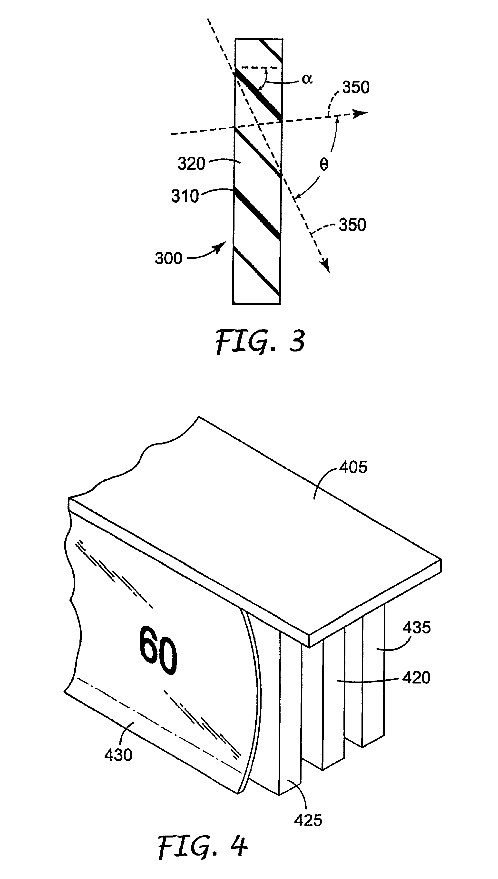
[0019]The present invention is directed generally to a display device in which two light control elements operate cooperatively with a source of illumination to limit the directionality of light emitted by the display. The light control elements control the light at least two directions. One of the light control elements further limits the directionality of reflected ambient light entering the display. In one aspect, use of the display device can reduce or eliminate reflections from surfaces proximal to the display, for example, both above and to the side of the display, insofar as the directionality, or viewing angle, of light emitted by t...


PUM

PropertyMeasurementUnit
Angleaaaaaaaaaa
Electrical resistanceaaaaaaaaaa
Antireflectiveaaaaaaaaaa

Abstract

A display device having an indicator interposed between two light controlling elements. The light controlling elements act in cooperation to restrict the viewing angle of the display in at least two directions. Only one of the light collimating elements restricts the angle of ambient light entering the display.

Description

FIELD OF INVENTION[0001]The present invention relates to displays, in particular displays used in applications where it is desired to control viewing angles.BACKGROUND[0002]A problem found in lighted instrument panel displays such as those in use in land vehicles, watercraft and aircraft is that light emitted by the display exits through a wide range of angles. Some of this light can strike nearby reflective surfaces such as a windshield or cockpit windows and be reflected back towards the operator of the craft. While sunlight generally prevents such reflections from being visible during the day, they are often clearly visible at night. Such reflections can create a dangerous situation by distracting the operator or even obscuring the operator's view.[0003]In addition to reflections from light emitted by the display, ambient light reflected from the viewing surface of the display toward the operator can obscure the display itself. The ambient light source can be, for example, light ...

Claims


Application Information

Patent Timeline
IPC IPC(8): B60K35/00G02B5/00G02F1/1335G02F1/13G02B1/11G02F1/133G02F1/13357G09F9/00
CPCB60K35/00G02B5/003B60K37/02G02F1/1323B60K2350/206G02F1/133524G02F2001/133607G02F1/133607B60K35/60B60K2360/20G02F1/1335
Inventor GAIDES, GARY E.
Owner 3M INNOVATIVE PROPERTIES CO
Why Eureka
Try Eureka