Attachment offset tooth eyelet

a technology of eyelet and offset tooth, which is applied in the field of eyelet offset mechanism, can solve the problems of time-consuming and lengthening the patient's time in orthodontic appliances, and achieve the effect of convenient holding the eyel

Inactive Publication Date: 2005-06-14
GRAHAM NEIL JOHN
View PDF3 Cites 3 Cited by
  • Summary
  • Abstract
  • Description
  • Claims
  • Application Information

AI Technical Summary

Benefits of technology

[0008]In another embodiment of the eyelet appliance all wire is used configured to resemble the mesh pad combination. Instead of the mesh pad, the wire is configured in an eyelet parallel to the lingual surface

Problems solved by technology

Once the tooth is in position it often has to be rotated 180 degrees which i

Method used


Image

  • Attachment offset tooth eyelet
  • Attachment offset tooth eyelet
  • Attachment offset tooth eyelet

Examples


Embodiment Construction

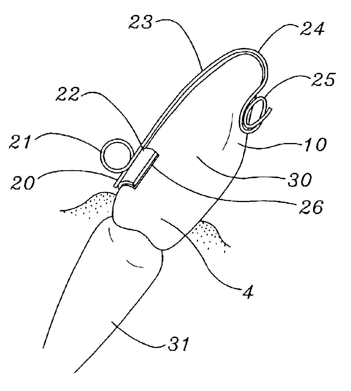
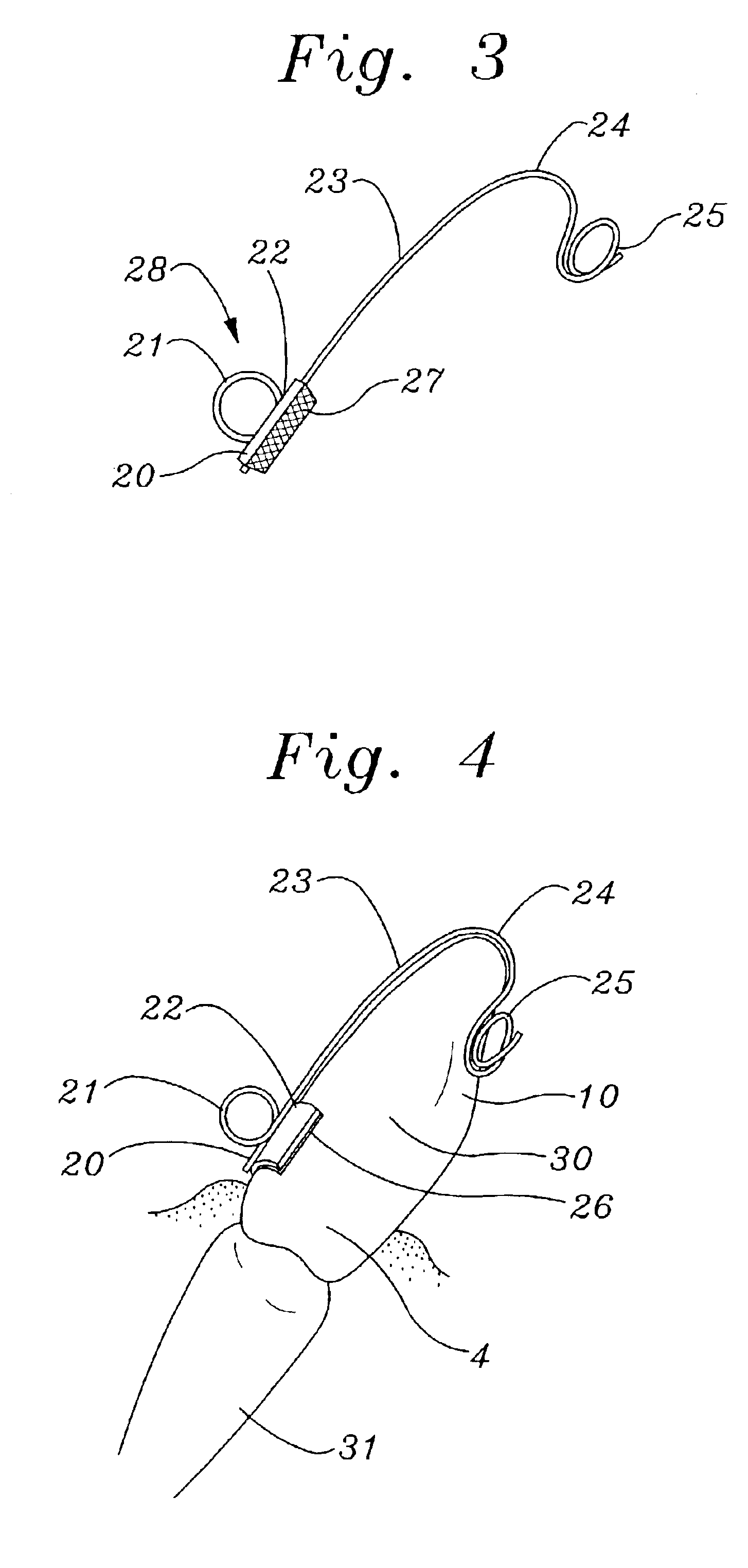
[0016]Referring to FIGS. 3 and 4, the attachable offset tooth eyelet has a stainless steel pad 26 with the mesh backing 27 for adhesion to a tooth 30 as in FIG. 4. Soldered or electro-welded to the occlusal surface of a stainless steel pad 26 is a wire member 28 of the attachable offset tooth eyelet comprised of 0.014-0.025 inch diameter stainless steel. The preferred embodiment is 0.020 inch diameter wire. The wire member 28 has a horizontal first leg 20 which is parallel to the metal pad 26. The horizontal first leg 20 is 2-4 mm in length and has the same axial direction as the lingual tooth surface 4 when the attachable offset tooth eyelet is positioned on the lingual surface of the tooth 4. The wire then turns at a right angle away from the tooth surface and forms an occlusal vertical eyelet 21 2-3 mm in diameter. The planar dimension of the vertical eyelet 21 is the same direction as the axial direction of the first leg 20. The wire continues from the vertical eyelet 21 and for...


PUM


Abstract

The invention is an orthodontic bondable offset tooth eyelet which is attached to the lingual surface of an impacted tooth placing an orthodontic force attaching eyelet on an unattachable labial or buccal surface, the labial placement assures the tooth will arrive in its final position rotationally correct.

Description

FIELD OF INVENTION[0001]The present invention is directed to an offset eyelet mechanism attachable to an impacted tooth during orthodontic procedures, the configuration of the eyelet allows the orthodontic pressure to be exerted to the center of the labial surface of an impacted tooth.BACKGROUND OF THE INVENTION[0002]The orthodontic procedure today for aligning an impacted tooth involves attaching, usually by bonding, a mesh backed metal pad with an eyelet to a surgically uncovered tooth. The patient is usually in a full orthodontic appliance to which an attachment is made to the labial eyelet of the impacted tooth. The attachment to the eyelet is a force which will move the impacted tooth towards the orthodontic appliance and into its aligned position. Often the only accessible surface of the impacted tooth for attaching the eyelet to is the lingual surface of the impacted tooth. This is especially true for palatally impacted maxillary cuspids. It is desirable to attach the orthodo...

Claims


Application Information

Patent Timeline
IPC IPC(8): A61C7/00
CPCA61C7/00
Inventor GRAHAM, NEIL JOHN
Owner GRAHAM NEIL JOHN
Why Eureka
Try Eureka