Tapping tool for use with drill press

a drill press and tapping tool technology, applied in the direction of drilling tools, drilling/drilling apparatus, thread cutting machines, etc., can solve the problems of excessive work space requirements, lack of ease of use, and high cost, and achieve the effects of convenient use, greater flexibility, and greater incidence of us

Inactive Publication Date: 2006-02-14
BLICK JOHN
View PDF23 Cites 16 Cited by
  • Summary
  • Abstract
  • Description
  • Claims
  • Application Information

AI Technical Summary

Benefits of technology

[0013]A tapping device is provided as an integral guided spindle tapper with spring return which is easily used in a drill press, milling machine, lathe or similar rotary powered machine typically employing a chucking device for the axial mounting of tools. The tapping device herein is utilized while such machines are in the un-powered state, taking advantage of the axial alignment and adjustability to accommodate a wide size variety of parts. An internal spring return allows for easy management of the tapping components during the tapping process and provides for axial retraction of the tap and tapping device from the tapped hole or bore to a position above and free from the part, an advantage usually not had outside of dedicated tapping stands having counter weights.
[0014]The ability of this tapping device to be used in a drill press allows the tapping device to take advantage of the axial adjustability available in axially adjustable quills and height adjustable tables of a typical drill press to allow for a far greater variety of size of parts to be tapped than available in a table top, tapper dedicated, fixed stand. Further, the tapper can be used in the field with any sort of guiding stable structure, which opens the possibility of performing very large to quite small size taps which can be performed anywhere. The moveable table of the drill press or similar machine, or the tail stock of a lathe enables the new tapping device herein far greater flexibility than is available conventionally.
[0015]The tapping device herein is configured to be used within a non-powered drill press or lathe or other device capable of holding a cylindrical object or extension being capable of being axially centered generally, and is to be powered by hand only. The tapping device has an upper projection for being axially fixed in, for example, a drill press. The drill press example is used because of its greater incidence in use and what is believed to be a greater simplicity of use from a vertical standpoint. The remainder of the body of the tapping device is rotatable with respect to the upper projection and includes side handles for providing handy mechanical advantage to the turning of the tapping device body. The end of the tapping device body opposite the upper projection includes a chuck or other adapter to facilitate the holding of a typical tapping tool.
[0016]The projection is connected to an internal shaft which engages the body of the tapping tool and is spring biased to draw the projection and internal shaft within the body of the tapping tool. Conversely, when the tapping tool is supported in, as an example, a drill press chuck, such spring urging acts to lift the body of the tapping tool in the direction of the projection. The number and nature of the springs which act between the internal shaft and the body of the tapping tool, as well as the dimensions noted can be widely varied to accommodate a variety of force versus displacement characteristics especially taking into account the mass of both the body of the tapping tool and its tap chuck. The tapping tool disclosed offers advantages in both guidance, alignment, and in disengagement from a just-tapped bore to minimize damage to the outermost threads of the just-threaded bore. The advantages of the tapper of the invention herein include (1) one piece unitized body for quick and easy utilization; (2) a return spring which not only prevents damage to tapped holes but holds the tapper in its upward most position to facilitate change of work piece; (3) a stroke length which insures adequate length for maintaining guidance throughout the full extent of tap travel; (4) a more “hands free” level of operation is enabled by facilitating the user's concentration on work piece alignment, starting the tap, and tap back out, all in a more controlled manner; (5) enhanced adjustability and part size accommodation; and (6) easy deployment and small space taken up upon storage.

Problems solved by technology

For some goals, the resulting design dictates a device which suffers in other areas.
Those other areas can include high cost, lack of ease of use, excessive work space requirements, and other disadvantages.
However, beginning the step of turning of the tap with advancement of the tap into the bore either caused the tap to lose its guiding connection with an axially non-moveable spindle, or required some other action by the user in operating a different mechanism to try and move the spindle.
However, the starting of the tapping process caused the tapping device pin to move down and eventually out of the bore, resulting in loss of alignment.
First, the axial length of the bore in the tapping tool and the insert may prohibit ease of removal of the tapping tool from the insert in order to easily change the tap.
As a result the device of Woods either disassembles or requires breaking the work piece setup each time a change of tap is needed.
Second, the device of Wood requires one hand to hold the tapping device upward and clear of the work piece while the work piece is being positioned.
Third, because of unsteadiness and the need for a third hand in positioning the work piece, the device of Wood naturally causes the user to operate with significant clearance over a work piece to avoid inadvertent contact between the tap and the work piece during pre-tap positioning.
This over clearance results in a significant portion of the length of telescoping travel to be utilized as clearance to make up for the ungainliness involved in work piece change.
This can cause the premature loss of guidance where the tapping device of Wood begins from a position too far down the rod insert.
Fourth, when the tapping tool of Wood is backed out of the tapped hole, a manual user may have a tendency to spin the tap at its point of departure from the now threaded bore to potentially damage the threads nearest the threaded bore opening.

Method used


Image

  • Tapping tool for use with drill press
  • Tapping tool for use with drill press
  • Tapping tool for use with drill press

Examples


Embodiment Construction

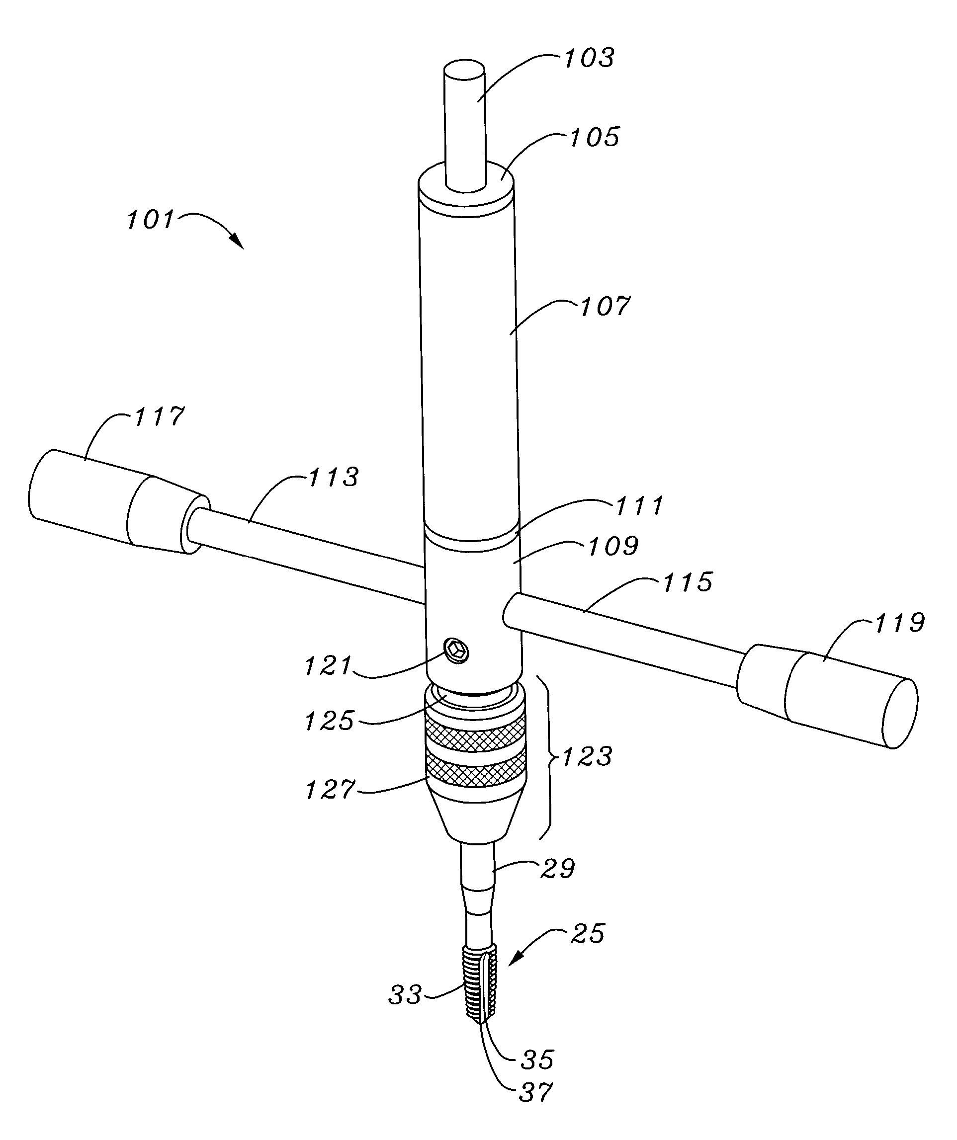
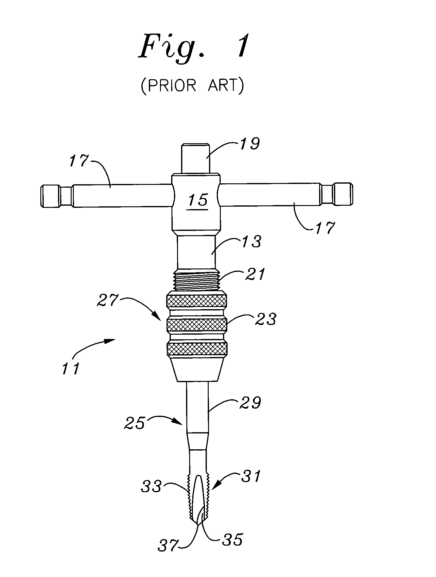
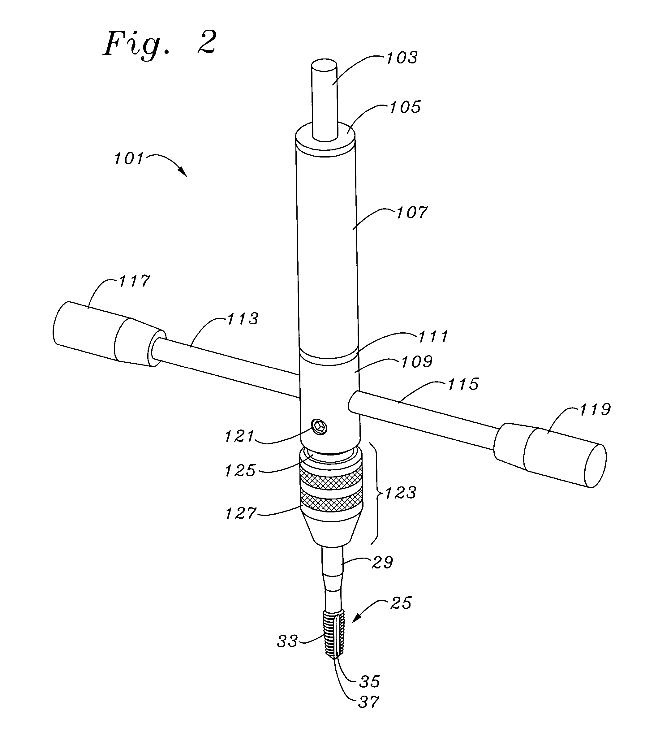
[0031]The description and operation of the invention will be best described with reference to prior art FIG. 1, which is a perspective view of a typical conventional hand tapper 11. Conventional tapper 11 has a main body 13 having an upper fitting 15 supporting a pair of side extending turning arms 17. Conventional tapper 11 has an upper nib 19 which may be used for support. Below the main body 13 is a threaded section 21 which may, with manually turned collar 23, be included as a chuck for holding a tap 25 in a conventional manner. Tap 25 has an upper end (not shown) designed to fit within a typical tap chuck and may vary in its specific shape, generally so long as it can be engaged by a chuck type of securing mechanism. Within or at the threaded section 21 and the manually turned collar 23 are other mechanism portions which make up the tap chuck which is shown by an arrow and designated with the numeral 27.

[0032]Tap 25 has a shaft 29 and a cutting head 31 typically having several ...


PUM

PropertyMeasurementUnit
forceaaaaaaaaaa
lengthaaaaaaaaaa
force biasaaaaaaaaaa

Abstract

A tapping device is configured to be used within a drill press or lathe or other device capable of holding a cylindrical object. The tapping device has an upper projection for being axially fixed in, for example, a drill press. The remainder of the body of the tapping device is rotatable with respect to the upper projection and includes side handles for providing handy mechanical advantage to the turning of the tapping device body. The end of the body opposite the upper projection includes a chuck for holding a typical tapping tool. The projection is connected to an internal shaft which engages the body of the tapping tool and is spring biased to draw the projection and internal shaft within the body of the tapping tool. Conversely, when the tapping tool is supported in, as an example, a drill press chuck, such spring urging acts to lift the body of the tapping tool in the direction of the projection. The number and nature of the springs which act between the internal shaft and the body of the tapping tool, as well as the dimensions noted can be widely varied to accommodate a variety of force versus displacement characteristics especially taking into account the mass of both the body of the tapping tool and its tap chuck. An adapter is provided for quick change of socket supported taps.

Description

FIELD OF THE INVENTION[0001]The present invention relates to improvements the field of tapping devices. More specifically, the present invention relates to a tapping device for use in a rotary operated machine such as a drill press, milling machine or lathe, along with a method which permits a cleaner, more controlled hand powered tap method, and which permits a more automatically controlled lifting force upon tap removal so as to better insure and preserve the threads of the tap nearest the tap opening.BACKGROUND OF THE INVENTION[0002]The many different types and numbers of tapping tools on the market reflect designs in which the designers pursued different goals which are served by the designs. For some goals, the resulting design dictates a device which suffers in other areas. Those other areas can include high cost, lack of ease of use, excessive work space requirements, and other disadvantages.[0003]Setting aside automated, highly specific dedicated machine tappers, as well as ...

Claims


Application Information

Patent Timeline
Patent Type & Authority Patents(United States)
IPC IPC(8): B23B45/12B23G1/00B23B31/08B23B51/00B23G1/48
CPCB23B31/083B23G1/48B23B2260/136Y10T408/637B23G2240/20Y10T408/643
Inventor BLICK, JOHN
Owner BLICK JOHN
Why Eureka
Try Eureka