
Developing device and image forming apparatus incorporating the same

a technology of developing device and image forming apparatus, which is applied in the direction of electrographic process apparatus, instruments, developers, etc., can solve the problems of deterioration of toner, increased cost of return roller, and complicated structure, and achieve excellent image quality

Inactive Publication Date: 2005-06-14
SEIKO EPSON CORP
View PDF18 Cites 30 Cited by
  • Summary
  • Abstract
  • Description
  • Claims
  • Application Information

AI Technical Summary

Benefits of technology

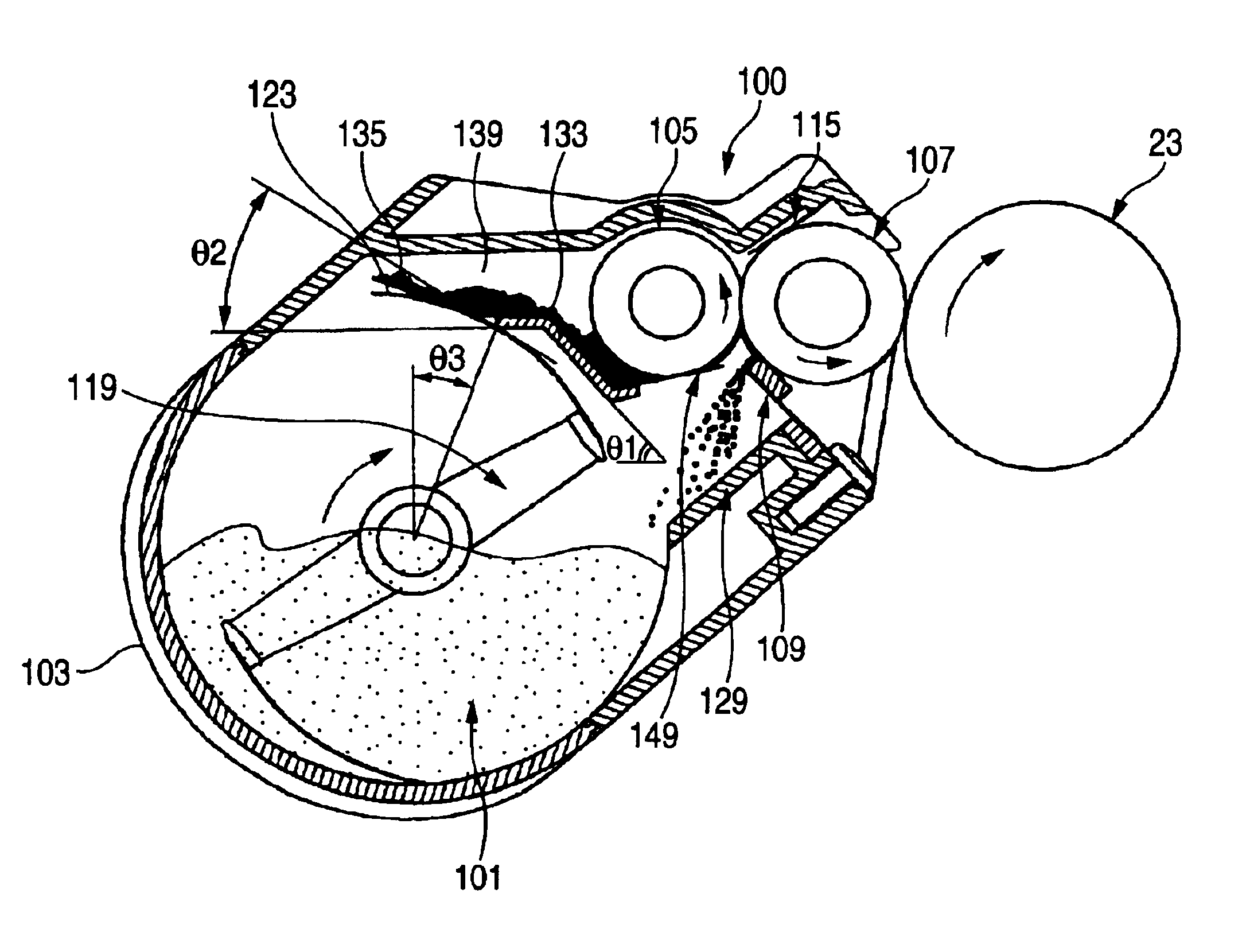
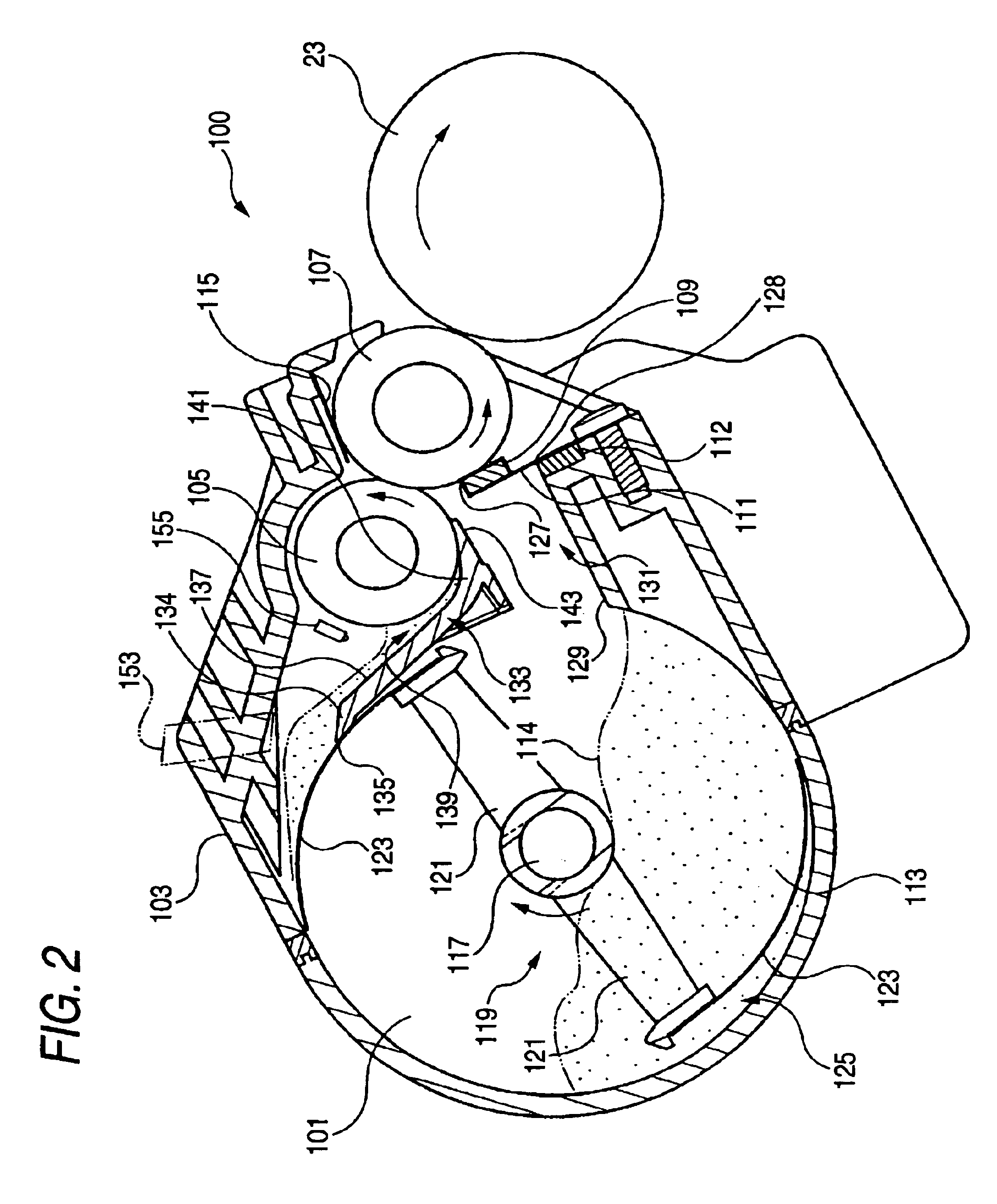
[0014]It is therefore an object of the invention to reduce mechanical stress on developer to thereby reduce fogging and density changes of the developer and keep good image quality, so that the running cost for expandable supplies can be reduced.
[0015]It is also an object of the invention to provide a developing device in which a sufficient volume of toner can be supplied to the upper portion of a supply roller stably, the circulating performance of toner scraped by a regulation blade is improved, and a uniform volume of toner can be supplied all over the lengthwise range of the supply roller stably.

Problems solved by technology

The structure becomes more complicated and the cost increases for the necessity of the return roller 223.
That results in degradation of the toner in an early stage.
Thus, fogging or solid density changes caused by the image degradation in an early stage are so conspicuous as to be a significant factor in reduction of image quality.
In addition, fogging increases the toner consumption so that the running cost for expandable supplies increases
As a result, in the opposite end portions of the supply roller 201, there is a probability that printing is impossible or printing unevenness is caused by flowing-out of the toner from the inner area.
This excess toner may cause a print in which the printing density is high in the opposite ends of paper.
This may cause another problem in terms of the relationship to paper that a print low in density in the opposite ends of the paper is made.
Thus, in a portion where the toner has fallen out, the toner is carried in patches on the circumferential surface of the supply roller so as to cause printing unevenness in a print.
When such a state occurs, not only does unevenness appear in toner volume on the surface of the developing roller, but the charge condition of the toner is also affected to cause trouble in quality of a print.

Method used


Image

  • Developing device and image forming apparatus incorporating the same
  • Developing device and image forming apparatus incorporating the same
  • Developing device and image forming apparatus incorporating the same

Examples


Embodiment Construction

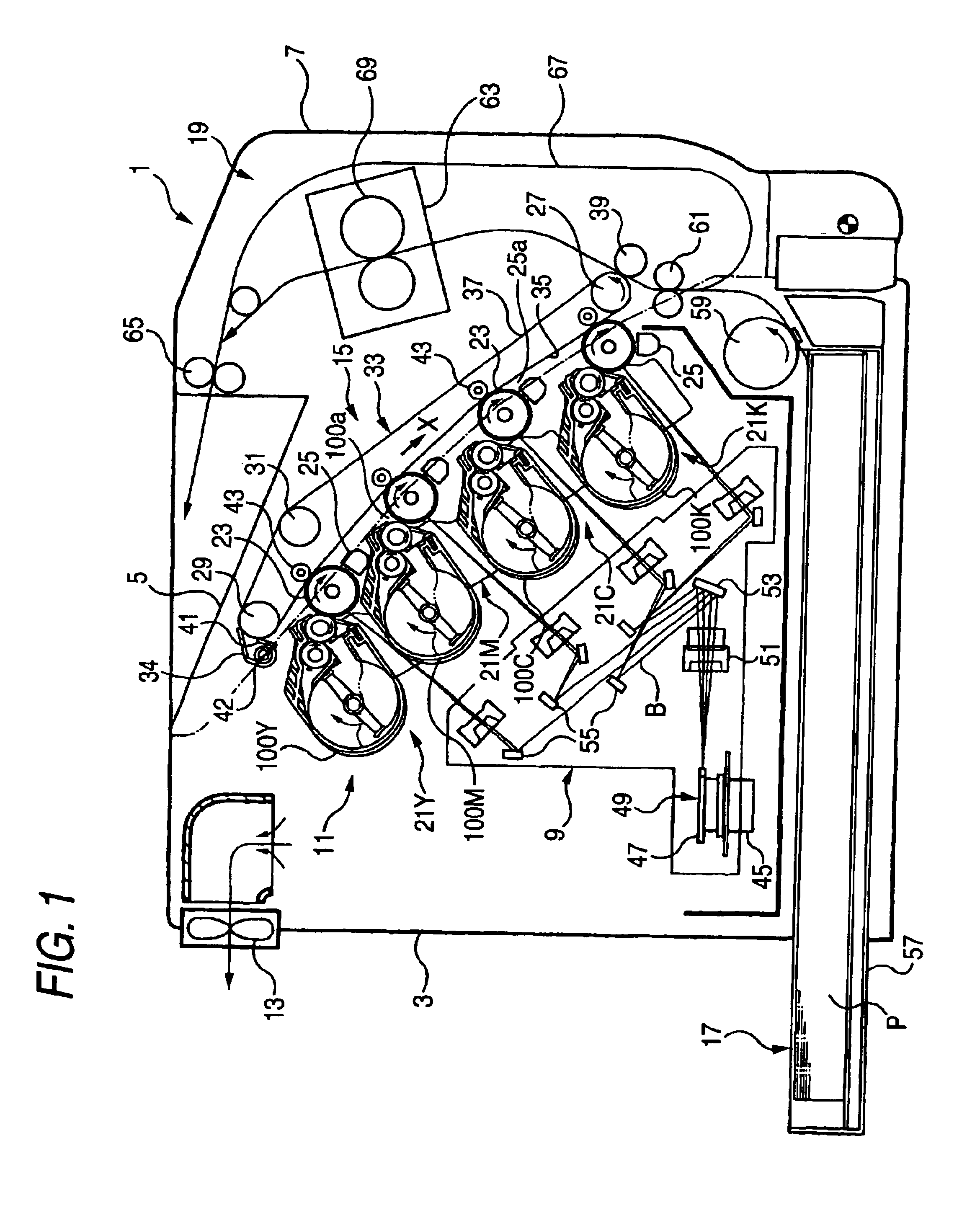
[0098]Preferred embodiments of the invention will be described below with reference to the accompanying drawings. To describe a developing device according to the invention, description will be made first on an example of a tandem type image forming apparatus to which the developing device is incorporated. In FIG. 1, an image forming apparatus 1 has a housing 3, a paper discharge tray 5 and a door body 7. The paper discharge tray 5 is formed above the housing 3. The door body 7 is openably provided in front of the housing. An exposure unit 9, an image forming unit 11, an air fan 13, a transfer belt unit 15 and a paper feeding unit 17 are disposed in the housing 3. A paper conveying unit 19 is disposed in the door body 7.

[0099]The image forming unit 11 has four image forming stations 21 in which four developing devices receiving different color toners can be set. Incidentally, the four image forming stations 21 are used for developing devices for yellow, magenta, cyan and black respe...


PUM


Abstract

A carrier carries developer. A regulation member disposed at a lower portion of the carrier to control an amount of the developer carried by the carrier. A first container disposed below the carrier to contain the developer therein. A guiding path guides developer dropped by the regulation member from the carrier, to the first container.

Description

BACKGROUND OF THE INVENTION[0001]The present invention relates to an image forming apparatus such as a copying machine or a printer, and particularly relates to a developing device for use in a tandem type image forming apparatus, and an image forming apparatus incorporating such a developing device.[0002]As systems for a developing device incorporated in an image forming apparatus, there are known a two-component developing system using toner and carrier in developer, and a one-component developing system using no carrier but only toner in developer. Of the one-component developing system, as a one-component color developing system, there are known a four-cycle rotary developing system in which developing devices for respective colors rotate to intermittently abut against a photoconductor in order to perform development on the photoconductor, and a tandem developing system in which development is carried out on photoconductors for respective colors with developing devices substanti...

Claims


Application Information

Patent Timeline
Patent Type & Authority Patents(United States)
IPC IPC(8): G03G15/08G03G9/08
CPCG03G9/0823G03G15/0822G03G2215/0838
Inventor YASUKAWA, SHINJIARUGA, TOMOEABE, NOBUMASANOMURA, YUJIROKUNUGI, MASANAO
Owner SEIKO EPSON CORP
Learn More