Cambering vehicle

a camera and vehicle technology, applied in the field of camera vehicles, can solve the problems of vehicle folding device, vehicle flexing application of unwanted flexing within the trailing arm, and more complex vehicles also include additional elements

Inactive Publication Date: 2005-06-21
PRODS OF TOMORROW
View PDF52 Cites 44 Cited by
  • Summary
  • Abstract
  • Description
  • Claims
  • Application Information

AI Technical Summary

Benefits of technology

[0002]The present invention relates to a cambering vehicle of the type having a single front wheel extending from a vertical steering stem's lower extremity and two rear wheels, each attached to one of a pair of horizontal trailing arms pivotally attached to the steering stem. Typically, handlebars attach to the steering stem's upper extremity to permit manipulation of the single wheel. Above the rear wheels on each of the trailing arms are platforms for the user to stand on while operating the vehicle. More particularly, the cambering vehicle of the present invention also includes a novel structure which may be readily folded for storage or transport, for example. Another embodiment of the cambering vehicle of the present invention includes a novel crossbar member spanning the two trailing arms.

Problems solved by technology

More complex vehicles also include additional elements, including brakes.
Such vehicles often suffer from the application of unwanted flexing within the trailing arm.
Also, such folding mechanisms typically include quick-release type features, which may cause folding of the device at inadvertent times, or which may be difficult to operate.
When the vehicle is cambered toward one side, such as the right side, the left trailing arm and thus the left rear wheel may be forced or caused to be moved upwardly away from the ground, or may not be suitably contacted with the ground.
Conversely, when the vehicle is cambered toward the other side, for example the left side, the right trailing arm and thus the right rear wheel may also be forced or caused to be moved upwardly away from the ground, or may not be suitably contacted with the ground, such that the vehicle may not be stable as it travels along the sinusoidal path.

Method used


Image

  • Cambering vehicle
  • Cambering vehicle
  • Cambering vehicle

Examples


first embodiment

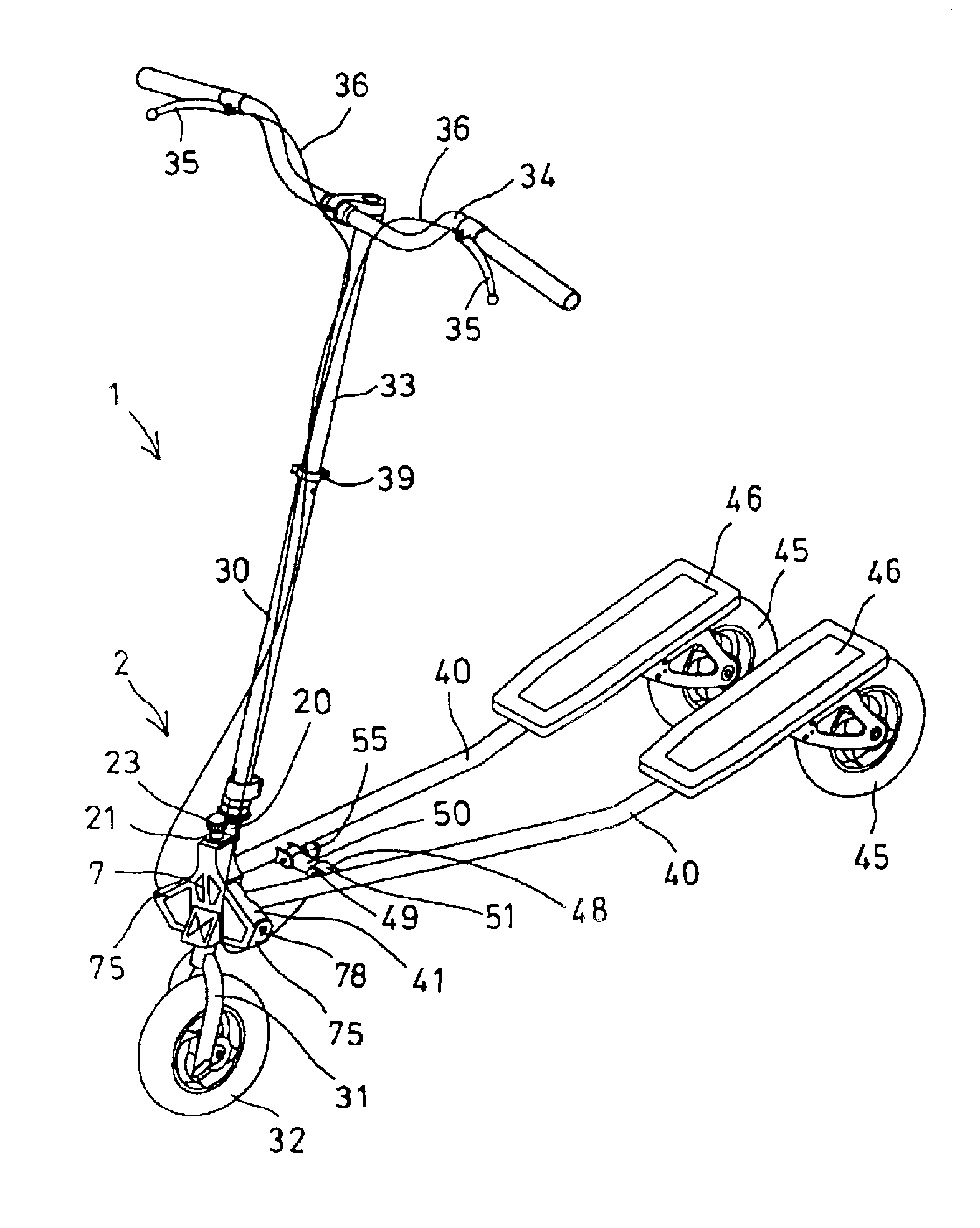
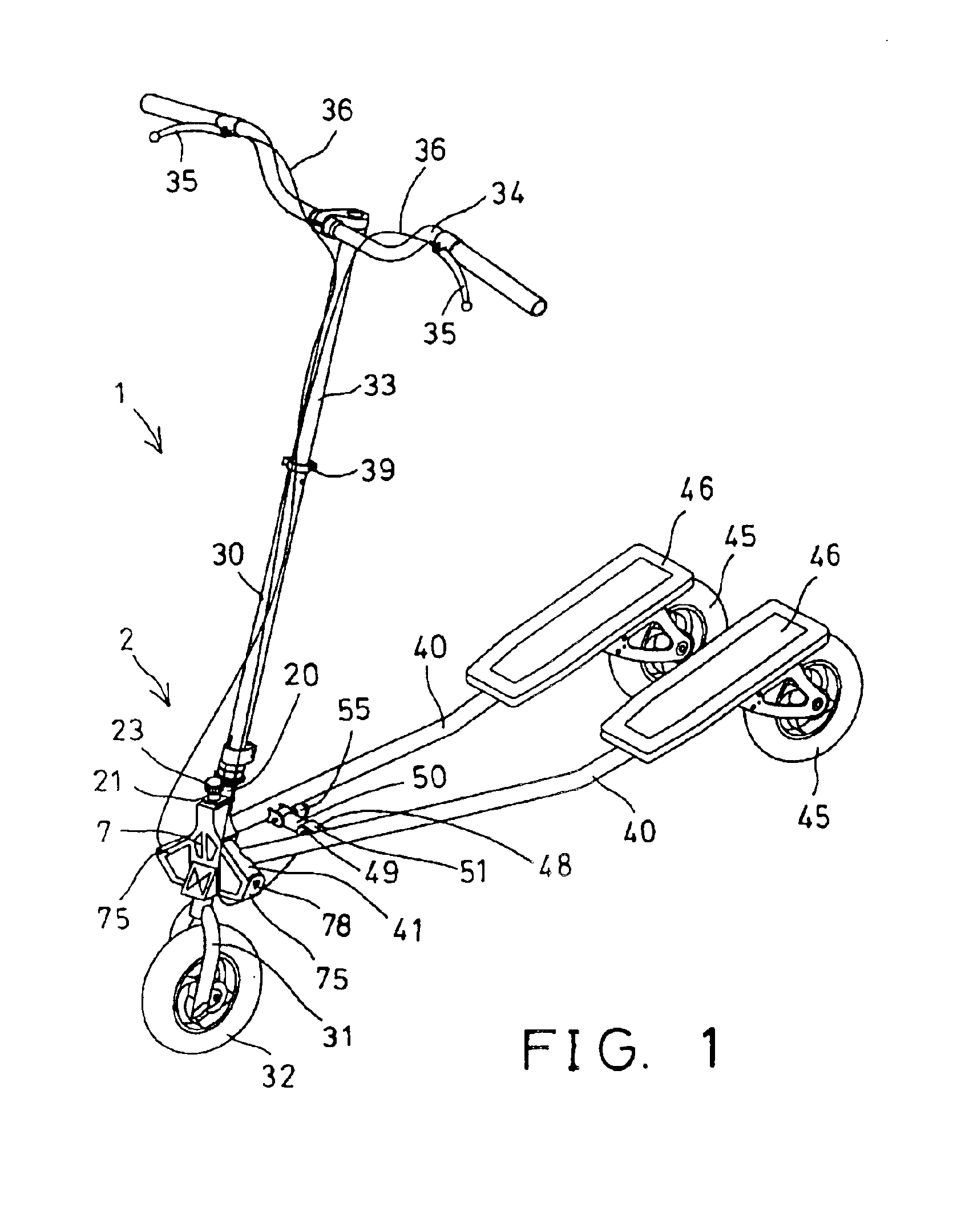
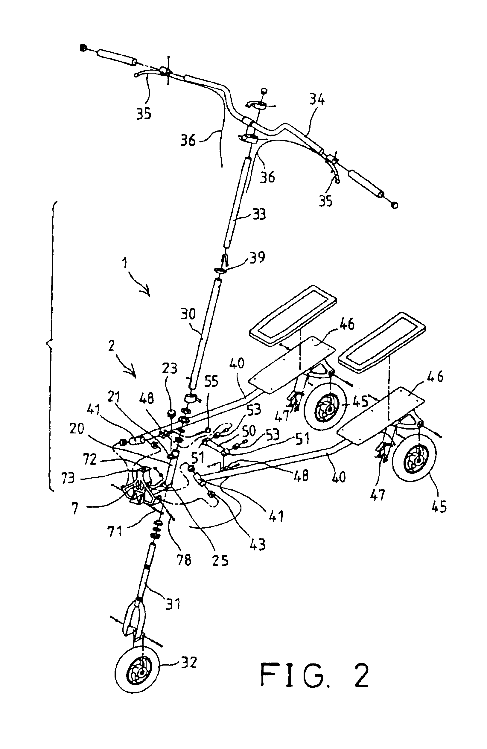
[0029]Referring to the drawings, and initially to FIGS. 1-6, a cambering vehicle 1 in accordance with the present invention comprises a front column 2 including a front tube 20, a steering shaft 30, a portion of which is rotatably engaged or disposed concentrically within the front tube 20, a front fork 31 attached to a bottom end of the steering shaft 30 to support a front wheel 32, and a handle 34 supported on a top end of the steering shaft 30.

[0030]The steering shaft 30 may preferably be provided with a stem 33 retractably received therein and extendible outwardly therefrom, or adjustably secured to the steering shaft 30 with a device such as a quick release clamp 39. The handle 34 is secured on top of the steering shaft 30 or on top of the stem 33 of the steering shaft 30, if so provided. One or more, and preferably two, brake hand grips 35 are attached to the handle 34 for braking purposes, and are coupled to cables 36 respectively.

[0031]As shown in FIG. 3, the front column 2 ...

third embodiment

[0051]Referring to FIGS. 13-17, a cambering vehicle 101 in accordance with the present invention comprises a front column 102 including a front tube 120, a steering shaft 130 rotatably engaged or disposed concentrically within the front tube 120, a front fork 131 attached to bottom of the steering shaft 130 to support a front wheel 132, and a handle 134 supported on top of the steering shaft 130.

[0052]The steering shaft 130 may further include a stem 133 retractably received therein and extendible outwardly therefrom, or adjustably secured to the steering shaft 130 with various mechanisms, such as a quick release clamp 139. The handle 134 is secured on top of the steering shaft 130 or on top of the stem 133 of the steering shaft 130. One or more, for example two, brake hand grips 135 may be attached to the handle 134 for braking purposes, and are coupled to cables 136 respectively. As will be discussed, the cables 136 are routed to braking element 147, respectively.

[0053]The front c...


PUM


Abstract

A cambering vehicle includes a front column, left and a right trailing arms each having a front portion pivotally attached to either the front column or a bracket attached thereto by a pivot axle which is preferably inclined relative to the bracket or the front column. A detachable latching device may be used to detachably latch the bracket, if so provided, and thus the trailing arms to the front column at the working position. The bracket and thus the trailing arm may be rotated relative to the front column to the folding position when the detachably latching device releases the bracket relative to the front column. The cambering vehicle may also include a link connect the trailing arms independent of the front column, and a braking mechanism to inhibit forward movement of the cambering vehicle.

Description

CROSS-REFERENCE TO RELATED APPLICATIONS[0001]The present continuation-in-part application relates to U.S. application Ser. No. 10 / 608,399, filed Jun. 23, 2003 and U.S. application Ser. No. 10 / 608,398, filed Jun. 23, 2003 now U.S. Pat. No. 6,880,840, the disclosures of which are hereby incorporated herein by reference.BACKGROUND OF THE INVENTION[0002]The present invention relates to a cambering vehicle of the type having a single front wheel extending from a vertical steering stem's lower extremity and two rear wheels, each attached to one of a pair of horizontal trailing arms pivotally attached to the steering stem. Typically, handlebars attach to the steering stem's upper extremity to permit manipulation of the single wheel. Above the rear wheels on each of the trailing arms are platforms for the user to stand on while operating the vehicle. More particularly, the cambering vehicle of the present invention also includes a novel structure which may be readily folded for storage or t...

Claims


Application Information

Patent Timeline
Patent Type & Authority Patents(United States)
IPC IPC(8): B62K21/00B62K3/00
CPCB62K3/002
Inventor CHUANG, JIN CHEN
Owner PRODS OF TOMORROW
Why Eureka
Try Eureka