Dental camera utilizing multiple lenses

a dental camera and lens technology, applied in the field of dental cameras, can solve the problems of difficult to visualize a dental structure using dental mirrors, significant limitations, and small mirror image, and achieve the effect of improving the visual effect of the patient, reducing the difficulty of patients undergoing surgery, and improving the patient's comfor

Inactive Publication Date: 2005-06-21
SIRONA DENTAL
View PDF74 Cites 60 Cited by
  • Summary
  • Abstract
  • Description
  • Claims
  • Application Information

AI Technical Summary

Benefits of technology

[0018]This invention teaches a dental camera having at least two lenses, one an intra-oral lense and one an extra-oral lens. The intra-oral lens preferably contains white LEDs to illuminate the inside of the mouth. The handpiece has a button located thereon for switching the mode of operation between the two lenses to effect intra-oral imaging and extra-oral imaging.

Problems solved by technology

These mirrors remain useful in certain respects, but significant limitations exist.
First, it is often difficult to visualize a dental structure using dental mirrors, because the image must be reflected into the viewer's line of sight.
Second, mirrors provide a relatively small image that can be difficult to see.
Third, providing the lighting necessary to illuminate fully the area being reflected by the mirror remains a challenge.
Furthermore, when using mirrors it is often difficult to communicate information to the patient or to other clinicians, because the image to be visualized is dependent upon the viewer's position relative to the mirror.
Second, they typically have built-in light sources which illuminate the area being visualized.
Dental cameras, however, have particular requirements not addressed by most endoscopes.
One challenge is to develop a camera suitable for both intra-oral and extra-oral imaging, each of which carries certain requirements which differ from the requirements carried by the other.
Unfortunately, while the Cooper structure offers some flexibility, it also requires magnification changing means, aperture changing means, and light dispersion changing means to be coupled with the focusing means, thereby adding an unnecessary layer of complexity into the design of the camera.
Furthermore, swapping the various objective lenses is clearly cumbersome for the dentist, and introduces a potential failure mechanism.
Unfortunately, this strategy still requires the dentist to adjust a knob, which is a cumbersome task, particularly when the dentist is in the middle of a procedure.
Williams et al. also shares a disadvantage with Cooper, in that the location of the lens on the handpiece is fixed.
More specifically, the location of the lens in these devices is on the distal tip, a location that is convenient for intra-oral use, but physically awkward for extra-oral use.
In addition, imaging parameters such as white balance cannot be easily optimized for specific applications.
Finally, in power constrained designs such as wireless cameras, the lamps that are required to provide illumination in intra-oral applications, but are not required for extra-oral applications, would often draw unnecessary power.
Wickholm et al., however, suffers from many of the same disadvantages as the Williams et al. patent.
Moreover, Wickholm et al. is not specific to, and not particularly suited for, the field of dentistry.
As explained above, providing a dental camera with the capability of effectively viewing the near field for intra-oral use and the far field for extra-oral use presents unique challenges due to certain inherent problems.
Namely, the two environments have significantly different imaging requirements that cannot be easily accommodated by one lens system.
Further challenges and differences relate to the aperture of the camera.
It has previously been impractical to house these systems (with either one or multiple lenses) entirely within the handpiece, as the resulting camera would be too large and bulky.
Most dental camera systems therefore suffer from limited portability.

Method used


Image

  • Dental camera utilizing multiple lenses
  • Dental camera utilizing multiple lenses
  • Dental camera utilizing multiple lenses

Examples


Embodiment Construction

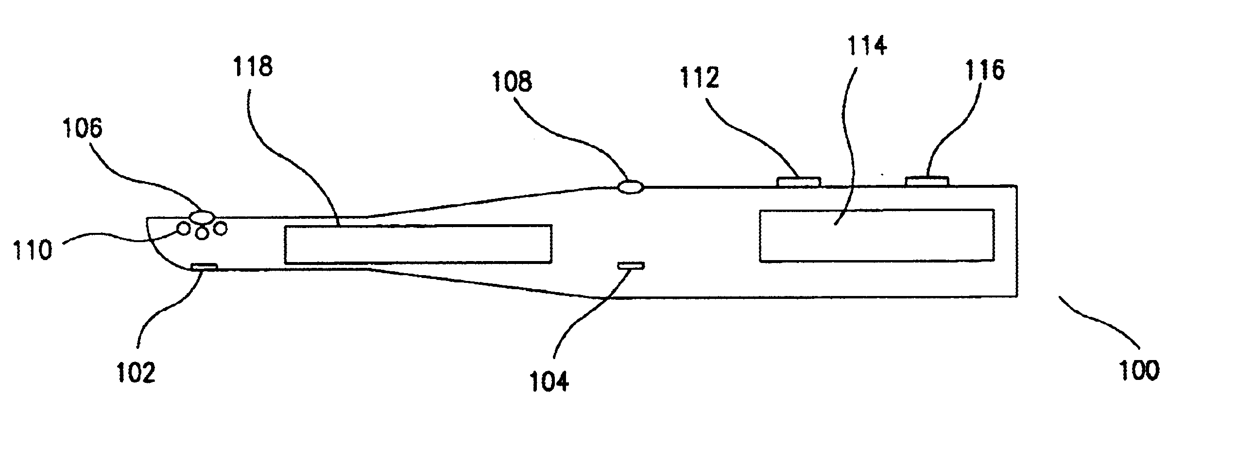
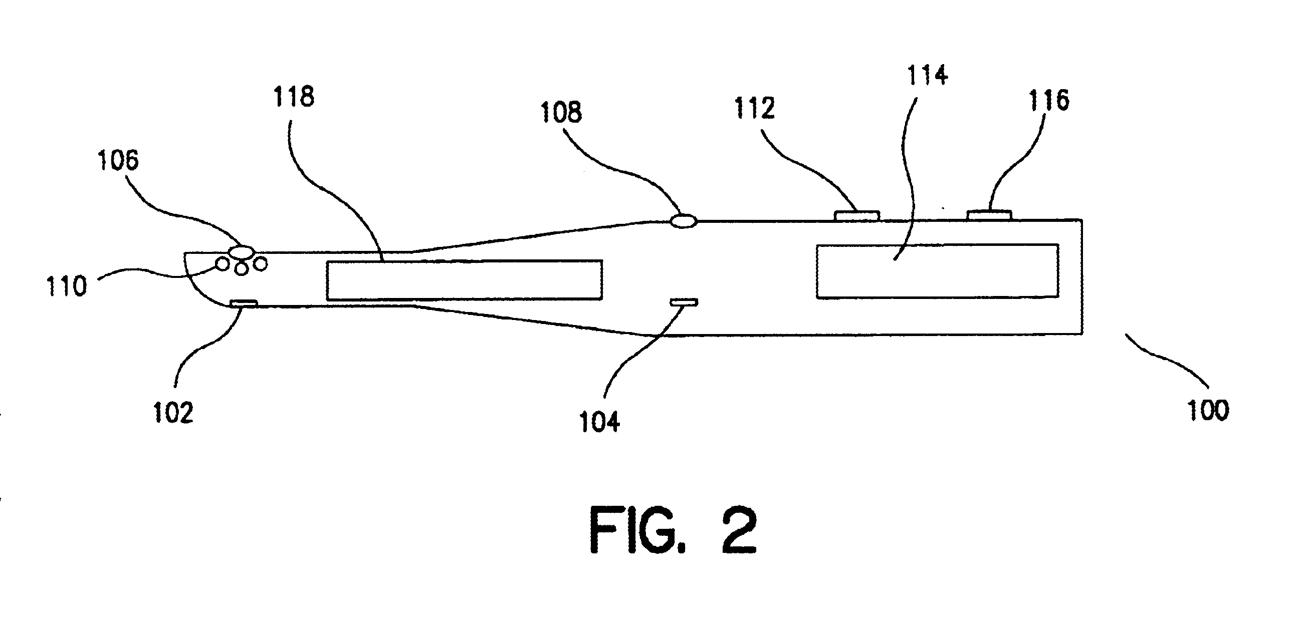
[0034]As explained above, the present invention relates to a dental camera having at least two lenses, selectable for switching between an intra-oral mode and an extra-oral mode. Each lens may be either a fixed focus or a variable-focus lens. A fixed-focus lens is a lens whereby the distance from the lens to the sensor is physically fixed. As a result, a fixed-focus lens creates a sharp image at only one distance to its subject. A variable-focus lens is a zoom lens, i.e., one in which focal length is variable. Elements inside a variable-focus lens shift their positions, enabling the lens to change its focal length, in effect providing one lens that has many focal lengths.

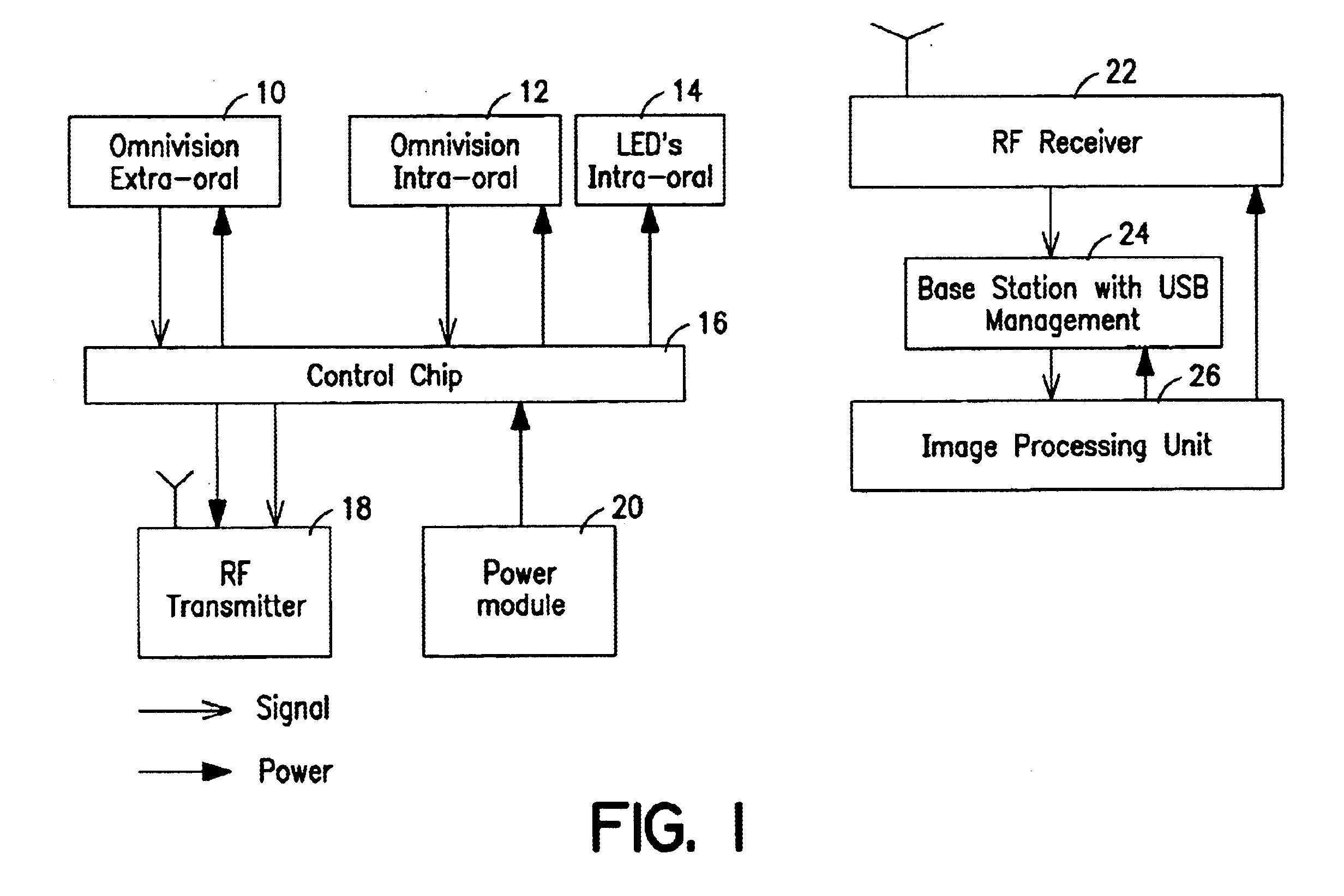
[0035]In order to implement the multiple lenses, in one embodiment of the present invention, the dental camera comprises two or more image sensors which generate image signals. The image sensors may be CMOS active pixel sensors (APS), such as for example an Omnivision OV7910N CMOS APS array. In accordance with the p...


PUM


Abstract

A dental camera is provided having multiple lenses. The dental camera has at least a first lens for use in an intra-oral mode, and at least a second lens for use in an extra-oral mode. The dental camera is switchable between the intra-oral mode and the extra-oral mode. Each lens is associated with an image sensor, for example, a CMOS active pixel sensor or a charge-coupled device.

Description

BACKGROUND OF THE INVENTION[0001]1. Field of the Invention[0002]This invention relates generally to the field of dental cameras, and more particularly to a dental camera system having at least two lenses selectable for either intra-oral or extra-oral use.[0003]2. Related Art[0004]For many years, clinicians in the dental industry used dental mirrors to more clearly visualize and diagnose hidden areas in a patient's mouth. These mirrors remain useful in certain respects, but significant limitations exist. First, it is often difficult to visualize a dental structure using dental mirrors, because the image must be reflected into the viewer's line of sight. Second, mirrors provide a relatively small image that can be difficult to see. Third, providing the lighting necessary to illuminate fully the area being reflected by the mirror remains a challenge. Furthermore, when using mirrors it is often difficult to communicate information to the patient or to other clinicians, because the image...

Claims


Application Information

Patent Timeline
Patent Type & Authority Patents(United States)
IPC IPC(8): A61B1/24
CPCA61B1/24
Inventor SCHICK, DAVID B.
Owner SIRONA DENTAL
Why Eureka
Try Eureka