Electric connector and socket connector

a socket connector and connector technology, applied in the direction of coupling contact members, coupling device connections, electric discharge lamps, etc., can solve the problems of insufficient coupling between the connectors, contact or the base may be damaged, and it is practically difficult to laterally extract the socket connector, etc., to achieve smooth extraction and reliable mounting of the socket connector

Inactive Publication Date: 2005-06-21
JST MFG CO LTD
View PDF7 Cites 25 Cited by
  • Summary
  • Abstract
  • Description
  • Claims
  • Application Information

AI Technical Summary

Benefits of technology

[0009]According to the embodiment of the invention, if the electric conductor is pulled to extract the socket connector, a force component acting generally parallel with the mounting surface can be converted into the force directed in the predetermined extracting direction by means of the cam surfaces. Accordingly, the socket connector may be smoothly extracted without causing an excessive load on both the connectors. When, on the other hand, the socket connector is mounted in place, the corresponding cam surfaces function to guide insertion of the socket connector thereby ensuring a reliable mounting of the socket connector.

Problems solved by technology

Furthermore, when the life of the battery expires, the user usually replaces it with a new one.
There may be a case where an inadequate connection between contacts results from an inadequate coupling between the connectors.
If an excessive force is applied to extract the socket connector, the contact or the base may be damaged.
However, it is practically difficult to laterally extract the socket connector in a state where the connector assembly is incorporated into a device.
In the compromise system, however, the socket connector is difficult to extract because the direction of extracting the socket connector differs from the direction in which the wires extend.
Furthermore, there is a fear of damaging both the connectors by forcibly extracting the socket connector.

Method used


Image

  • Electric connector and socket connector
  • Electric connector and socket connector
  • Electric connector and socket connector

Examples


Embodiment Construction

[0022]A preferred embodiment of the invention will be described with reference to the accompanying drawings.

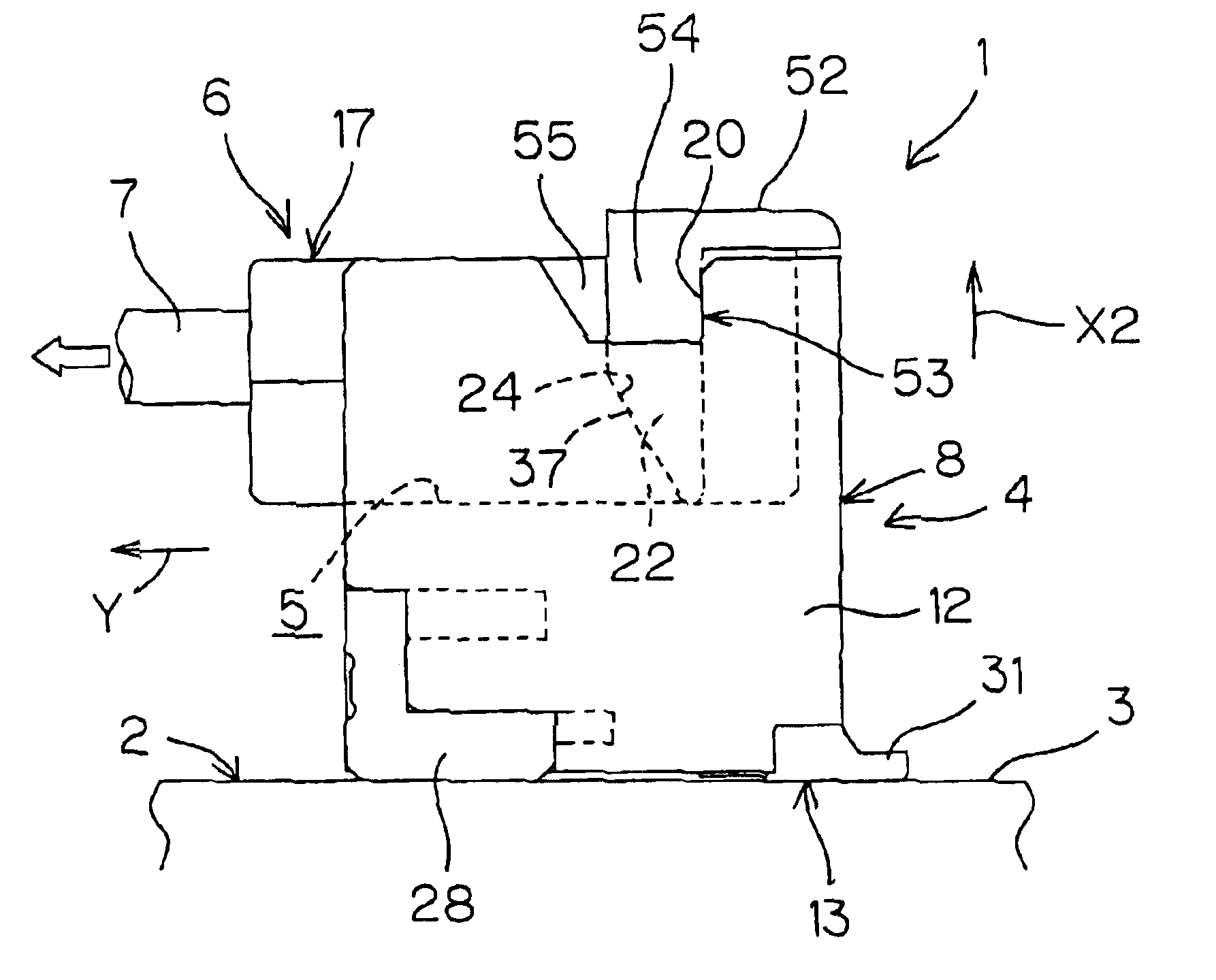
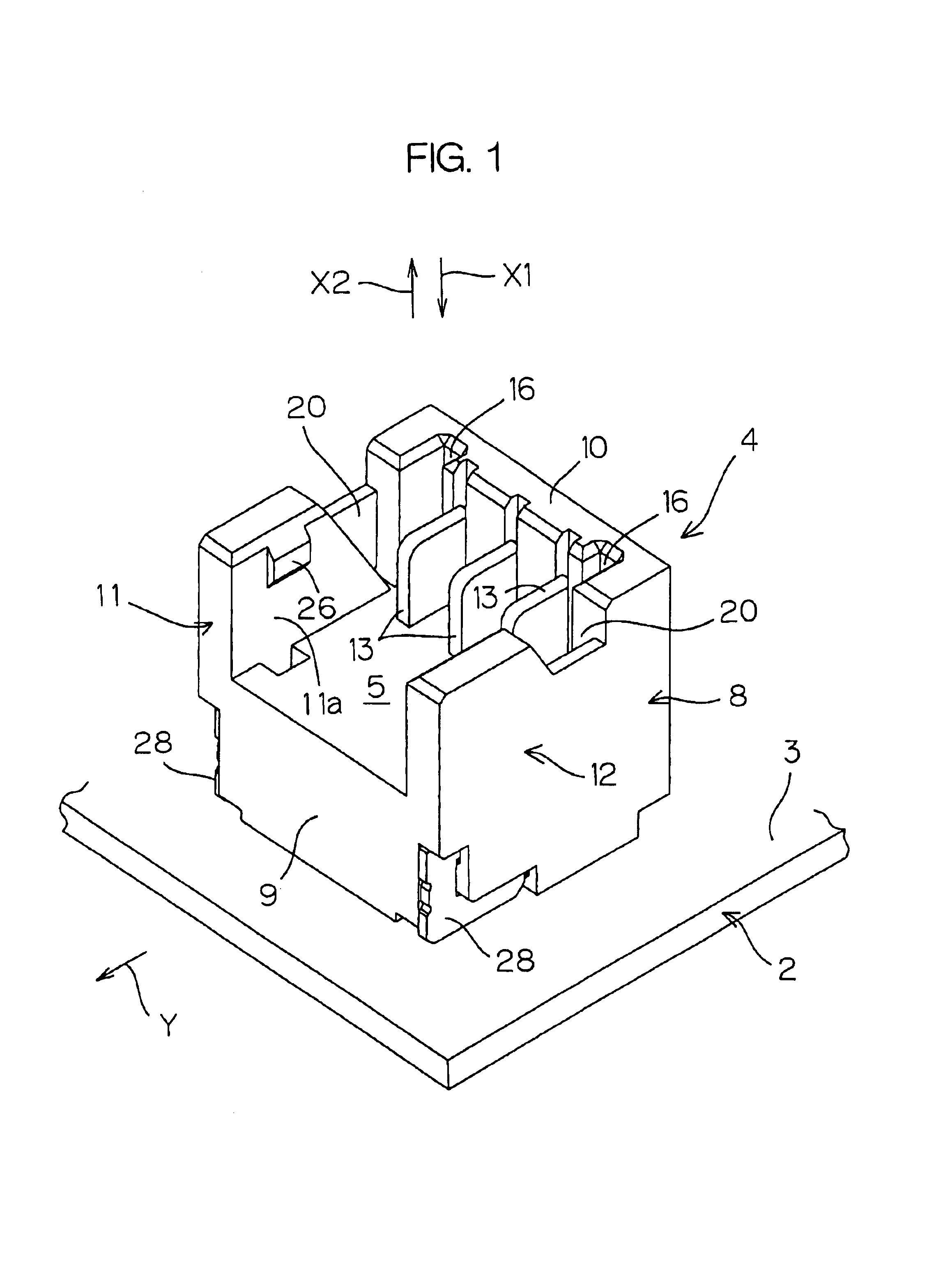
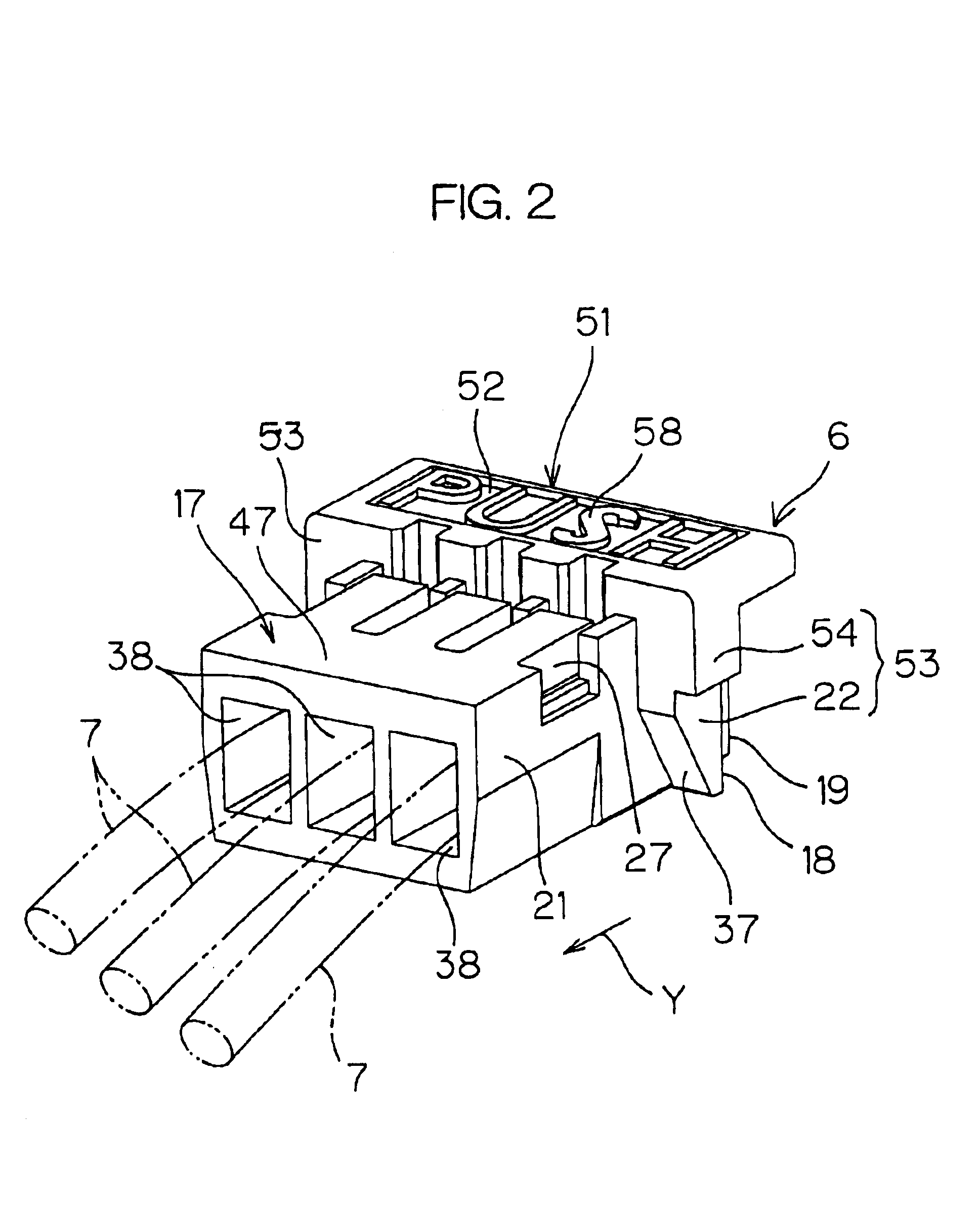
[0023]FIGS. 1 and 2 are schematic perspective views showing a base connector and a socket connector included in an electric connector according to one embodiment of the invention. FIG. 10 is a side view showing the electric connector wherein both the connectors are in connection. Referring to these figures, the electric connector 1 includes a base connector 4 fixedly soldered onto a mounting surface 3 of a base 2, and a socket connector 6 forming a pair with the base connector 4 and inserted in or extracted from an inserting space 5 of the base connector 4. The electric connector 1 is used for connection between a base such as of a cellular phone, PHS or the like and a battery.

[0024]Referring to FIGS. 1 and 2, the inserting space 5 of the base connector 4 opens along a direction orthogonal to and away from the mounting surface 3 of the base 2 (the direction representing a dire...


PUM


Abstract

An electric connector, comprising a base connector (4) fixed onto a mounting surface (3) and a socket connector (6) extracted from the inserting space (5) of the base connector (4) along the extracting direction (X2) generally orthogonal to the mounting surface (3), wherein, when an electric conductor (7) extending in the direction parallel with the mounting surface (3)(Y) is pulled in the direction parallel with the mounting surface (3)(Y), a tension is converted into a force in the direction of extracting the socket connector (6) (X2) by the activation of the cam surface (24) of the base connector (4) and the cam surface (37) of the socket connector (6), whereby the socket connector (6) can be removed smoothly.

Description

TECHNICAL FIELD[0001]The present invention relates to an electric connector including, for example, a base connector fixed onto a surface of a base and a socket connector extractable from the base connector along a direction orthogonal to the base, as well as to the socket connector.BACKGROUND ART[0002]The recent years have seen a dramatic proliferation of cellular phones and PHS (Personal Handyphone System). In the case of the cellular phone and the like, a user having purchased a device needs to mount a connector of an integral battery to a connector of a base or the like. Furthermore, when the life of the battery expires, the user usually replaces it with a new one.[0003]Thus, the connector is mounted or removed by such a user who is not accustomed to the handling of the connectors. There may be a case where an inadequate connection between contacts results from an inadequate coupling between the connectors. If an excessive force is applied to extract the socket connector, the co...

Claims


Application Information

Patent Timeline
Patent Type & Authority Patents(United States)
IPC IPC(8): H01R13/629H01R13/115H01R13/11H01R13/46
CPCH01R13/62905H01R13/113H01R12/79H01R12/716H01R13/633
Inventor SHIMIZU, KAZUOMISASAKI, SHOICHI
Owner JST MFG CO LTD
Why Eureka
Try Eureka