Energy management system for automotive vehicle

Inactive Publication Date: 2005-06-21
MIDTRONICS
View PDF289 Cites 152 Cited by
  • Summary
  • Abstract
  • Description
  • Claims
  • Application Information

AI Technical Summary

Problems solved by technology

However, this technique does not take into account the actual condition of the battery as the voltage across the battery is not an accurate representation of the bat

Method used


Image

  • Energy management system for automotive vehicle
  • Energy management system for automotive vehicle
  • Energy management system for automotive vehicle

Examples


Embodiment Construction

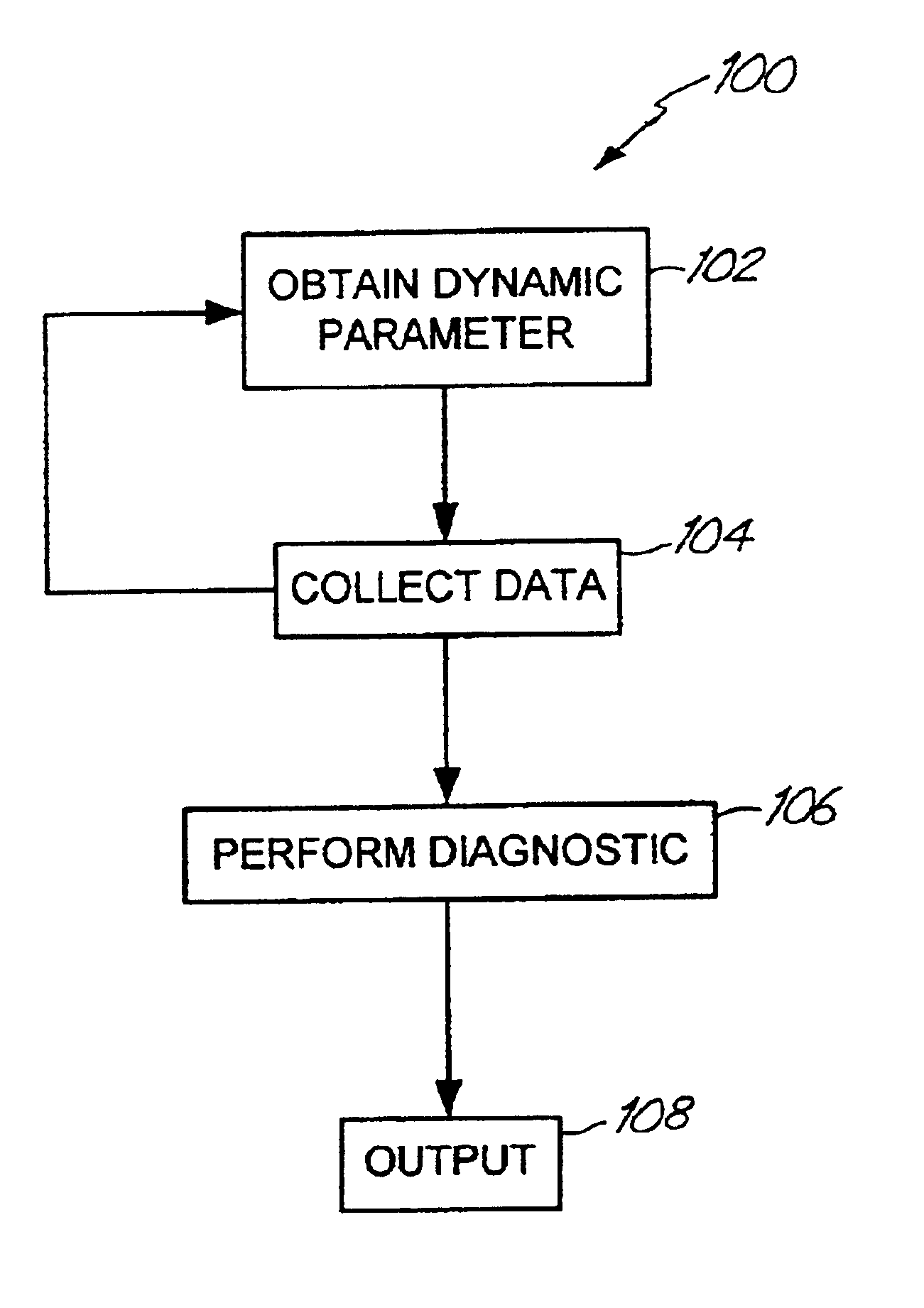
[0014]The present invention offers an apparatus and method for monitoring the condition of the battery and controlling charging of the battery. Such a method and apparatus can be part of a general energy management system for a vehicle.

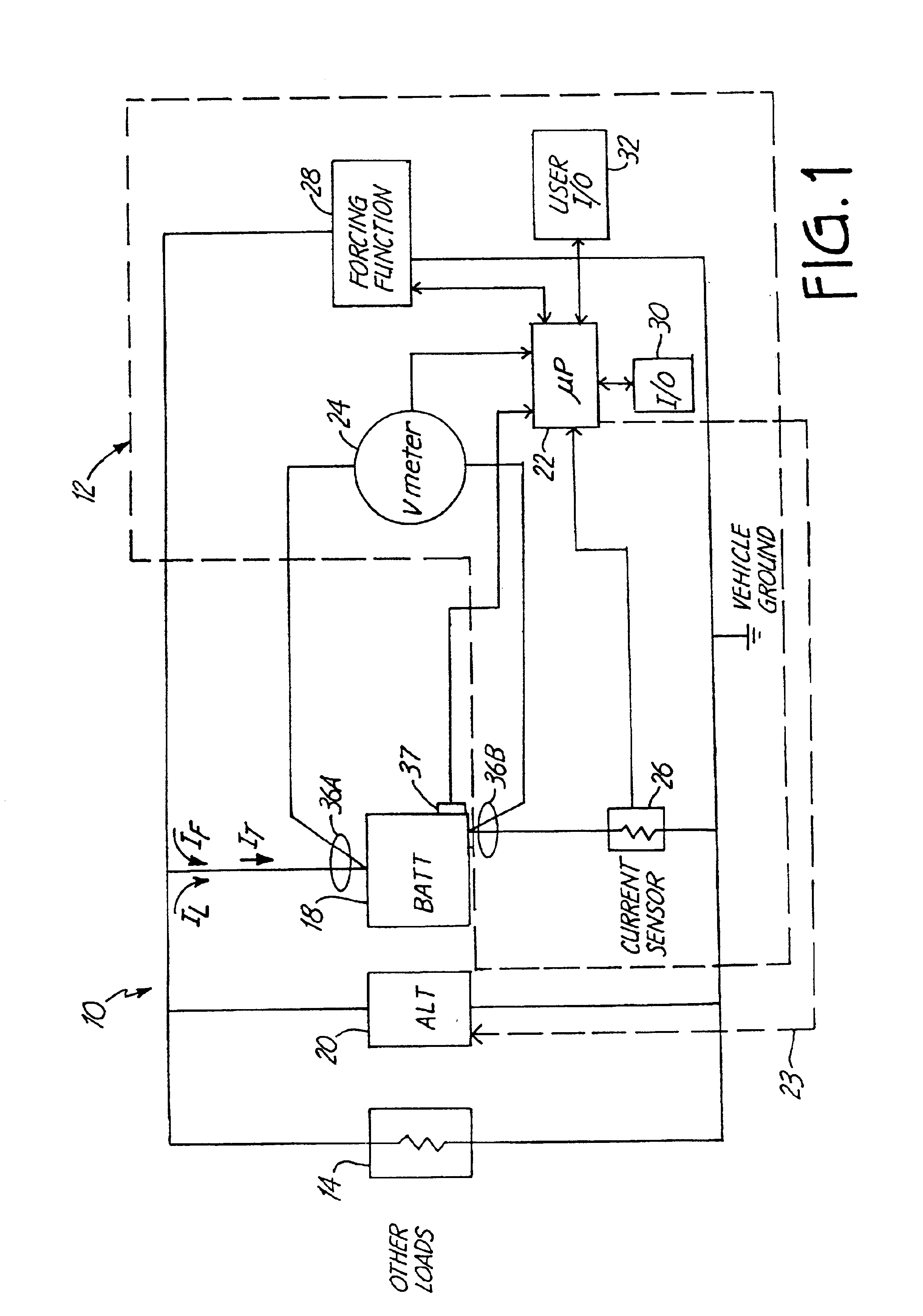
[0015]FIG. 1 is a simplified block diagram showing an automotive vehicle 10 which includes a battery monitor 12 in accordance with one embodiment of the present invention. Vehicle 10 includes vehicle loads 14 which are shown schematically as an electrical resistance. A battery 18 is coupled to the vehicle load 14 and to an alternator 20. Alternator 20 couples to an engine of the vehicle 10 and is used to charge battery 18 and provide power to loads 14 during operation.

[0016]In general, automotive vehicles include electrical systems which can be powered when the engine of the vehicle is operating by a generator, or alternator. However, when the engine is not running, a battery in the vehicle is typically used to power the system. Thus, the standard gen...


PUM


Abstract

A battery monitor is provided for use with a battery of an automotive vehicle. The battery monitor can provide real time battery condition measurements and can selectively control the charging of the battery through an alternator of the vehicle based upon the measured battery condition.

Description

[0001]The present invention is a divisional of application Ser. No. 09 / 564,740, filed May 4, 2000 is now U.S. Pat. No. 6,331,762 which claims priority to Provisional Application Ser. No. 60 / 132,622, filed May 5, 1999, and entitled AUTOMOTIVE VEHICLE BATTERY CHARGING SYSTEM; U.S. Provisional Application No. 60 / 165,208, filed Nov. 12, 1999, and entitled ENERGY MANAGEMENT SYSTEM FOR AUTOMOTIVE VEHICLE; and Provisional Application Ser. No. 60 / 175,762, filed Jan. 12, 2000, and entitled ENERGY MANAGEMENT SYSTEM FOR AUTOMOTIVE VEHICLE, which are incorporated herein by reference in their entirety.BACKGROUND OF THE INVENTION[0002]The present invention relates to automotive vehicles. More specifically, the present invention relates to an energy management and monitor system for a battery of an automotive vehicle.[0003]Automotive vehicles powered by combustion engines typically include a battery. The battery is used to power the electrical system when the engine is not running. Additionally, t...

Claims


Application Information

Patent Timeline
IPC IPC(8): G01R31/36H02J7/16H02J7/00G01R31/00
CPCG01R31/3627G01R31/3648H02J7/163H02J7/0004H02J7/0008H02J7/0077H02J7/008G01R31/007G01R31/3662G01R31/3675G01R31/3693G01R31/385G01R31/3647G01R31/389G01R31/374H02J7/00041H02J7/00036H02J7/00712H02J7/00047
Inventor BERTNESS, KEVIN I.
Owner MIDTRONICS
Why Eureka
Try Eureka