Functionality switching for MICR printing

a micr printing and functional switching technology, applied in the field of electrographic printing machines, can solve the problems of poor toning and fusing efficiency of micr toners, adversely affecting the image quality of printed characters, and difficult to achieve and maintain an adequate dispersion of heavy iron oxide particles in toner resin,

Active Publication Date: 2005-06-21
HEIDELBERG DIGITAL +1
View PDF9 Cites 23 Cited by
  • Summary
  • Abstract
  • Description
  • Claims
  • Application Information

AI Technical Summary

Benefits of technology

[0018]The present invention may be implemented into an electrographic printer capable of accepting different types of toner. The printer senses the insertion of a developing station using a certain type of toner, such as MICR toner. Upon sensing the toner type, the printer sets its operational parameters to optimal settings for that toner. According to another aspect of the invention, the printer enables certain security settings upon insertion of a toner type, such as MICR toner, that is used for secure printing.

Problems solved by technology

The relatively heavy loading of iron oxide in conventional MICR toner for electrographic MICR printing has been observed to adversely affect the image quality of the printed characters, however.
It is difficult to achieve and maintain an adequate dispersion of the heavy iron oxide particles in the toner resin.
In addition, the toning and fusing efficiencies of MICR toners are poorer than normal (i.e., non-MICR) toners, because of the magnetic loadings present in the MICR toner.
Accordingly, the image quality provided by MICR toner is often poorer than those formed by normal toner, unless the printing machine makes significant adjustments in its printing process.
Unauthorized use of these numbers on payment documents can facilitate fraud and theft.

Method used


Image

  • Functionality switching for MICR printing
  • Functionality switching for MICR printing
  • Functionality switching for MICR printing

Examples


Embodiment Construction

[0023]The preferred embodiment of this invention will now be described in connection with an electrographic printer, by way of example, because this invention is contemplated to be particularly beneficial in such an application. It will be appreciated by those skilled in the art having reference to this specification that this invention can also be used in any type of electrographic system, of any size or capacity. As such, this description is provided by way of example only, and is not intended or contemplated to limit the true scope of the invention as claimed.

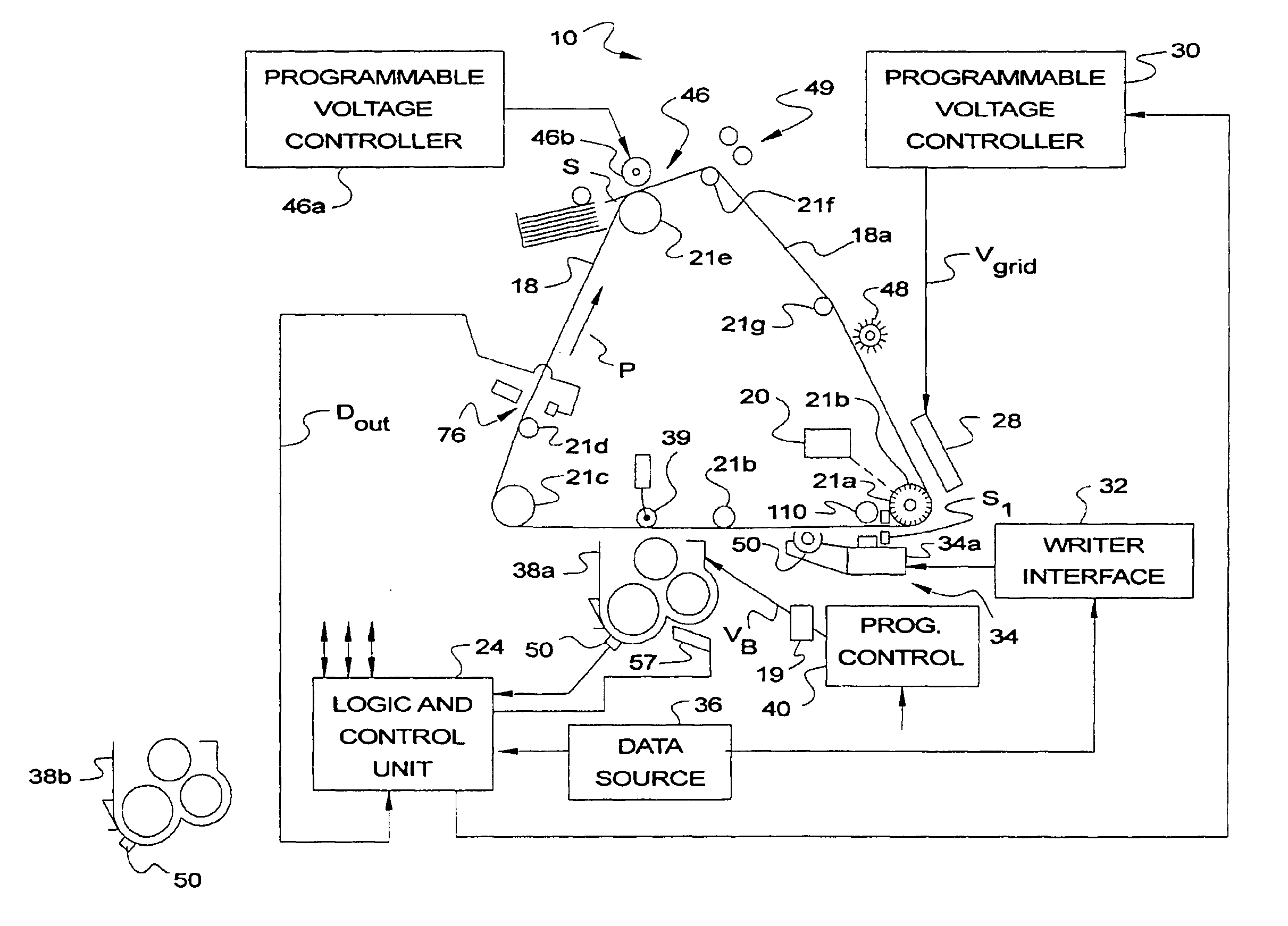
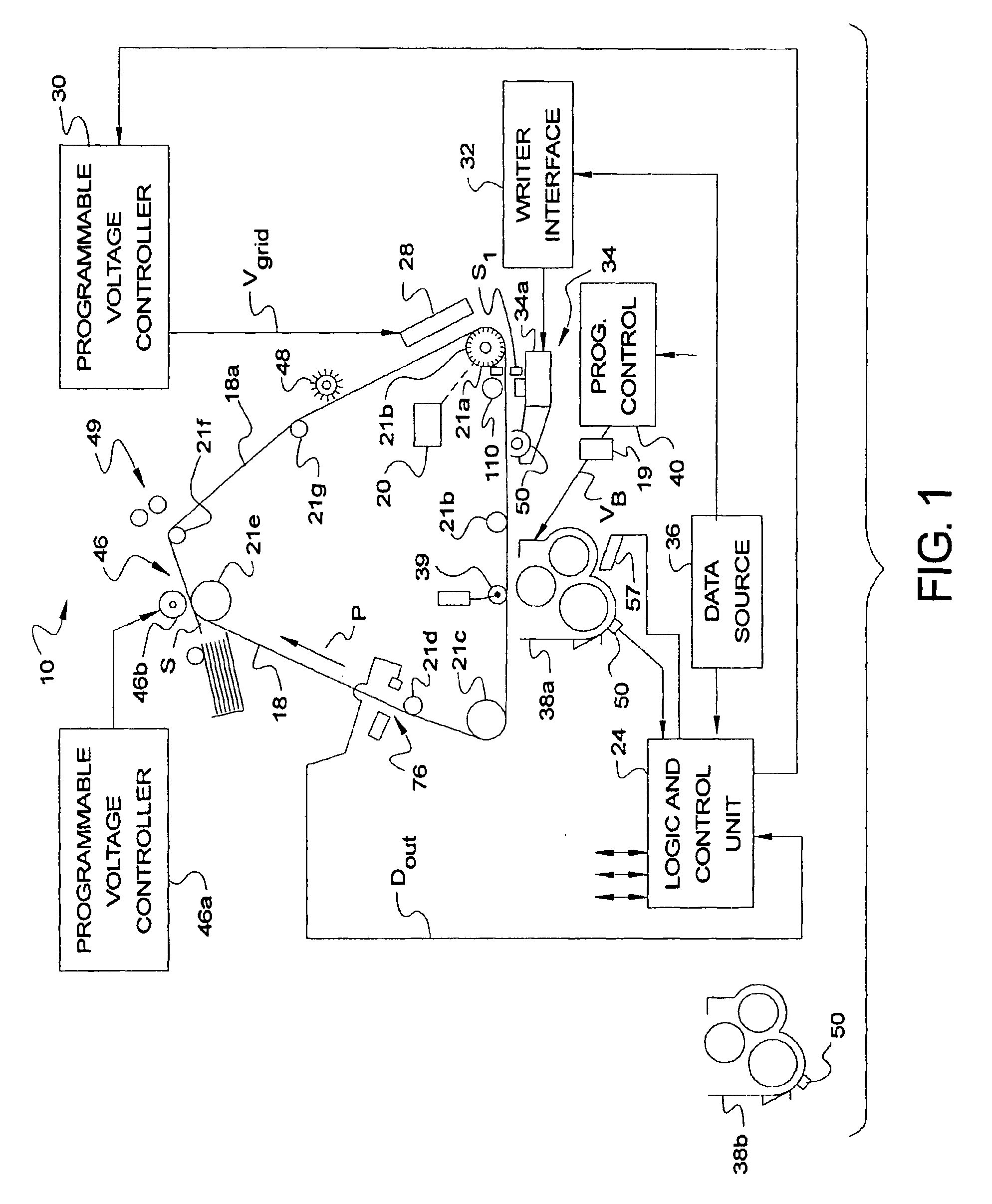
[0024]Referring now to FIG. 1, printer machine 10 according to the preferred embodiments of the invention will now be described. The exemplary printing machine 10 is illustrated in a general schematic sense, to provide a general context for the preferred embodiments of the invention; it is contemplated that this invention will be applicable to a wide range of printing machines. An example of a preferred model of printing mac...


PUM


Abstract

An electrographic printing machine (10) operable in combination with an installed one of a plurality of developing, or toning, stations (38a, 38b), is disclosed. Each of the plurality of toning stations (38a, 38b) is associated with a toner type, with one of the toning stations (38a) associated with Magnetic Ink Character Recognition (MICR) toner. Each toning station (38a, 38b) has an indicator (50), for example a resistor, that can be interrogated or measured by the printing machine (10) when installed, so that the printing machine (10) is aware of the type of toner to be used. If a MICR toning station (38a) is installed, a set of process setpoints and parameters are used that optimize MICR printing; if a normal toning station (38b) is installed, a different set of process setpoints and parameters adapted for the normal toner is used. Also in response to detecting that the MICR toning station (38a) is installed, the printing machine (10) enables certain security functions, such as privilege-level control of MICR fonts and secure files, and also such as disabling features such as automatic reprinting.

Description

CROSS-REFERENCE TO RELATED APPLICATIONS[0001]This application claims priority to U.S. Provisional Application Ser. No. 60 / 415,221 titled FUNCTIONALITY SWITCHING FOR MICR PRINTING filed Oct. 1, 2002 and which is incorporated herein in it's entirety by reference.FIELD OF THE INVENTION[0002]The present invention electrographic printers, and more particularly to electrographic printing machines operable in combination with an installed one of a plurality of developing, or toning, stations.BACKGROUND OF THE INVENTION[0003]This invention is in the field of electrographic printing, and is more specifically directed to the electrographic printing of documents suitable for reading by Magnetic Ink Character Recognition (MICR) technology.[0004]Electrographic printing has become the prevalent technology for modem computer-driven printing of text and images, on a wide variety of hard copy media. This technology is also referred to as electrographic marking, electrostatographic printing or markin...

Claims


Application Information

Patent Timeline
Patent Type & Authority Patents(United States)
IPC IPC(8): G03G15/00
CPCG03G15/0121G03G15/50G03G2215/0013
Inventor CRICHTON, JOHN F.
Owner HEIDELBERG DIGITAL
Why Eureka
Try Eureka