Vehicle locating system

a technology for locating systems and vehicles, applied in navigation instruments, program control, instruments, etc., can solve problems such as affecting the visual appeal of the car, affecting the safety of the vehicle, and being more susceptible to damag

Inactive Publication Date: 2005-06-21
STEERING SOLUTIONS IP HLDG +1
View PDF15 Cites 59 Cited by
  • Summary
  • Abstract
  • Description
  • Claims
  • Application Information

AI Technical Summary

Benefits of technology

[0005]In another embodiment, the vehicle locating system includes a first cellular telephone within the vehicle, the first cellular telephone including a first receiver and a first transmitter; a first GPS receiver within the vehicle and in operable communication with the first cellular telephone, the first GPS receiver is configured to determine a location of the vehicle; a hand-held device including: a direction indicator, a second cellular telephone, the second cellular telephone including a second receiver and a second transmitter, and a second GPS receiver in operable communication with the second cellular telephone, the second GPS receiver is configured to determine a location of the hand-held device; and wherein the first GPS receiver provides the location of the vehicle to the first cellular telephone, and the direction indicator is configured to point in a direction of the vehicle in response to a comparison of the location of the vehicle and the location of the hand-held device.

Problems solved by technology

Problematically, when such devices are made to be tall, they are also very bulky and more susceptible to being damaged by the wind.
Another drawback of visual indicators is that they must be located on the exterior of the vehicle.
Because visual indicators are located on the exterior of the vehicle, they detract from the visual appeal of the car.

Method used


Image

  • Vehicle locating system
  • Vehicle locating system
  • Vehicle locating system

Examples


Embodiment Construction

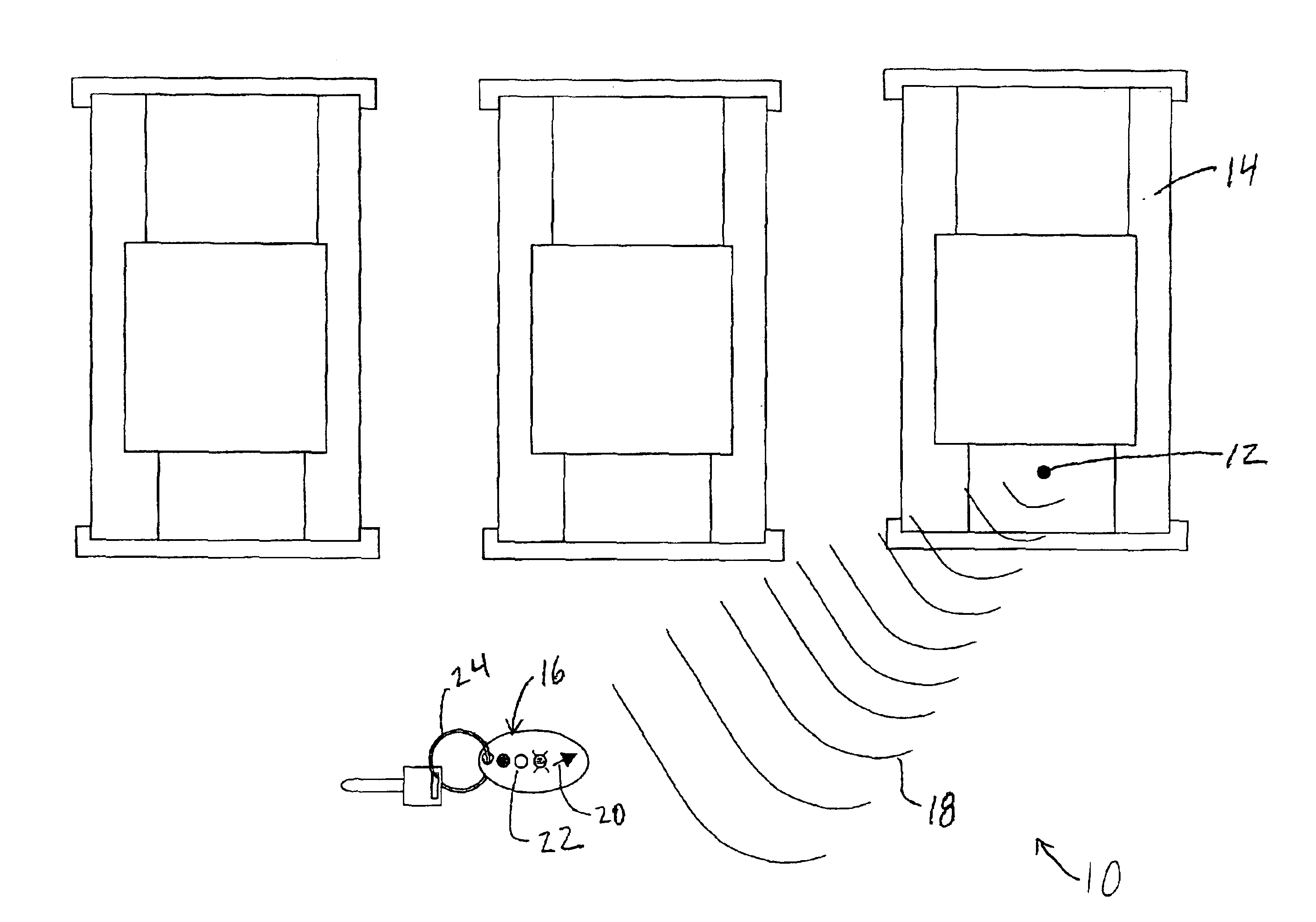
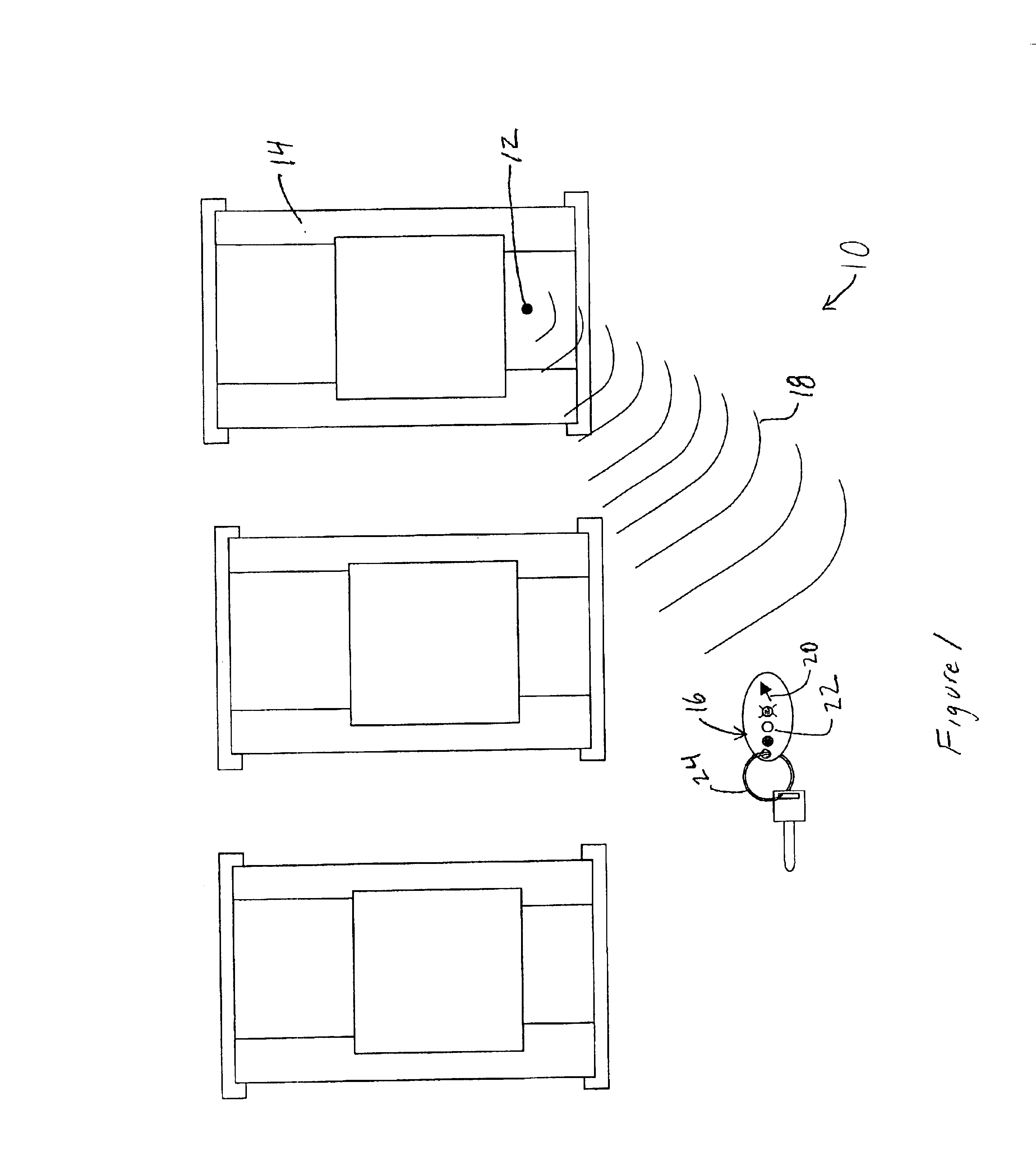
[0012]Referring to FIG. 1, a vehicle locating system is shown generally at 10. Vehicle locating system 10 includes a transmitter 12 coupled to a vehicle 14, and a hand-held device 16 configured to receive a location signal 18 transmitted by transmitter 12. Visible on the hand-held device 16 is a direction indicator 20 and a proximity indicator 22. Direction indicator 20 points in the direction of transmitter 12, which is the source of signal 18. A person holding the hand-held device 16 can determine the direction of vehicle 14 by viewing direction indicator 20. Proximity indicator 22 indicates the intensity of the direction signal 18 received at the hand-held device 16. A person holding the hand-held device 16 can approximate a distance between the vehicle 14 and the hand-held device 16 by viewing proximity indicator 20. In the embodiment of FIG. 1, hand-held device 16 is a key fob. Disposed on the key fob is a key retaining device 24. Key retaining device 24 may include, for exampl...


PUM


Abstract

A vehicle locating system includes a first transmitter within the vehicle, the first transmitter is configured to transmit a location signal; and a key fob including: a receiver, a direction indicator, and wherein the direction indicator is configured to point towards the first transmitter in response to receipt of the location signal by the receiver. In another embodiment, the vehicle locating system includes a first cellular telephone within the vehicle; a first GPS receiver within the vehicle and in operable communication with the first cellular telephone, the first GPS receiver is configured to determine a location of the vehicle; a hand-held device including: a direction indicator, a second cellular telephone, and a second GPS receiver in operable communication with the second cellular telephone, the second GPS receiver is configured to determine a location of the hand-held device; and wherein the first GPS receiver provides the location of the vehicle to the first cellular telephone, and the direction indicator is configured to point in a direction of the vehicle in response to a comparison of the location of the vehicle and the location of the hand-held device.

Description

BACKGROUND OF THE INVENTION[0001]Many devices have been designed to help a driver find his or her vehicle. Typically, such devices include a visual indication means that is attached to the car's exterior. Such visual indication means extend above other cars in the lot so that the driver can easily see the location of his or her car.[0002]While visual indication means are effective, they have many drawbacks. For example, such devices rely on visual recognition, which requires that the device be tall enough to allow visibility over tall vehicles. Problematically, when such devices are made to be tall, they are also very bulky and more susceptible to being damaged by the wind. Another drawback of visual indicators is that they must be located on the exterior of the vehicle. Because visual indicators are located on the exterior of the vehicle, they detract from the visual appeal of the car.BRIEF SUMMARY OF THE INVENTION[0003]Disclosed herein is a vehicle locating system comprising: a fi...

Claims


Application Information

Patent Timeline
Patent Type & Authority Patents(United States)
IPC IPC(8): G08G1/005G01S19/36
CPCG08G1/005G01S5/0072
Inventor ARMSTRONG, RAY G.PERISHO, JR., ROBERT A.KELL, CURTIS N.
Owner STEERING SOLUTIONS IP HLDG
Why Eureka
Try Eureka