Self-piercing rivet setting apparatus and system

a rivet setting and self-piercing technology, applied in metal working equipment, metal-working equipment, manufacturing tools, etc., can solve the problems of insufficient connection strength, restricted rivet-driving direction, and rivet oblique piercing of the receiving-side workpiece, so as to reduce or eliminate the restriction on the rivet-driving direction and the effect of sufficient undercut amoun

Inactive Publication Date: 2005-06-28
NEWFREY
View PDF11 Cites 24 Cited by
  • Summary
  • Abstract
  • Description
  • Claims
  • Application Information

AI Technical Summary

Benefits of technology

[0008]According to the above self-piercing rivet setting apparatus, until the front end of the leg of the self-piercing rivet starts piercing the receiving-side workpiece adjacent to the die, the first die member allows the leg to be driven into the workpiece in a straight direction. Then, when the leg starts piercing the receiving-side workpiece, the front end of the leg is widely expanded in its radial outward direction by the second die member to provide a sufficient undercut amount. The sufficient undercut amount can achieve an adequate connecting force even if the receiving-side workpiece has a thin thickness of one-half or less of that of the other workpiece (or the punch-side workpiece). This makes it possible to reduce or eliminate the restriction on the rivet-driving direction with respect to the workpieces. Thus, the complicated operation of turning over either the setting apparatus or the workpieces as in the conventional setting apparatus can be skipped or omitted to thereby achieve a speedy setting operation. Further, the setting operation can be carried out even in the conventionally impossible rivet-driving direction. The eliminated restriction on the rivet-driving region provides widened applicable area or region suitable for the self-piercing rivet setting operation.
[0011]According to this system, the first self-piercing rivet setting apparatus allows the leg to be driven into the workpiece in a straight direction until the front end of the leg of the self-piercing rivet starts piercing the receiving-side workpiece adjacent to the die. Then, when the leg starts piercing the receiving-side workpiece, the front end of the leg is widely expanded in its radial outward direction by the second self-piercing rivet setting apparatus, to provide a sufficient undercut amount. The sufficient undercut amount can achieve a desired connecting force even if the receiving-side workpiece has a thin thickness of one-half or less of that of the punch-side workpiece. This makes it possible to reduce or eliminate the restriction on the rivet-driving direction with respect to the workpieces. Thus, the complicated operation of turning over either the setting apparatus or the workpieces as seen in the conventional setting apparatus can be skipped or omitted to achieve a speedy setting operation. Further, the setting operation can be carried out even in the conventionally impossible rivet-driving direction. The eliminated restriction on the rivet-driving region provides widened applicable area or region suitable for the self-piercing rivet setting operation.

Problems solved by technology

In a conventional self-piercing-rivet driving operation, if the punch-side workpiece has a greater thickness in a rivet-driving direction than that of the receiving-side workpiece adjacent to the die, a radial piercing length, that is, an undercut amount of the leg of the rivet obliquely piercing the receiving-side workpiece can be reduced, resulting in insufficient connecting strength.
The above limitation (or the need for preventing the receiving-side workpiece from having a thickness of one-half or less of the thickness of the other workpiece in a self-piercing rivet driving region of the workpieces) imposes the restriction on the rivet-driving direction.
However, the rivet-setting operation cannot be carried out at a desirably increased speed due to a time required for turning over the setting apparatus or the workpieces.
Besides, the turning-over operation per se can get into difficulties due to the restrictions on the workpiece shapes, the rivet-driving region and other factors.

Method used


Image

  • Self-piercing rivet setting apparatus and system
  • Self-piercing rivet setting apparatus and system
  • Self-piercing rivet setting apparatus and system

Examples


Embodiment Construction

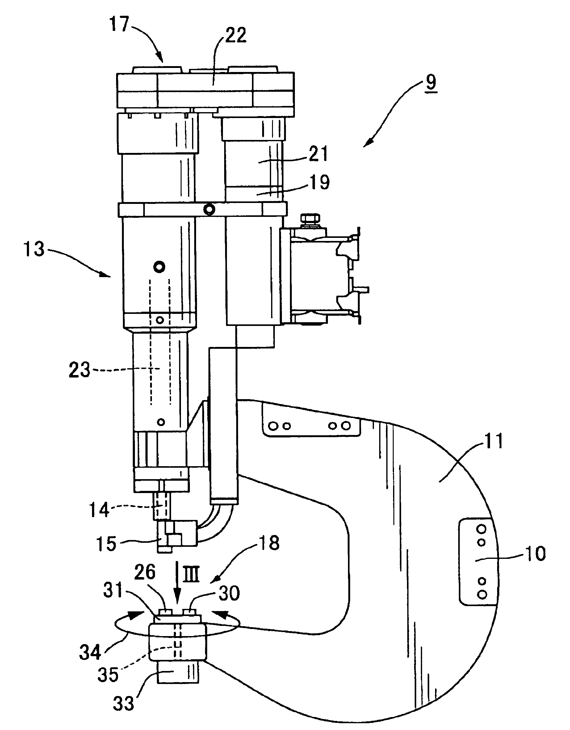
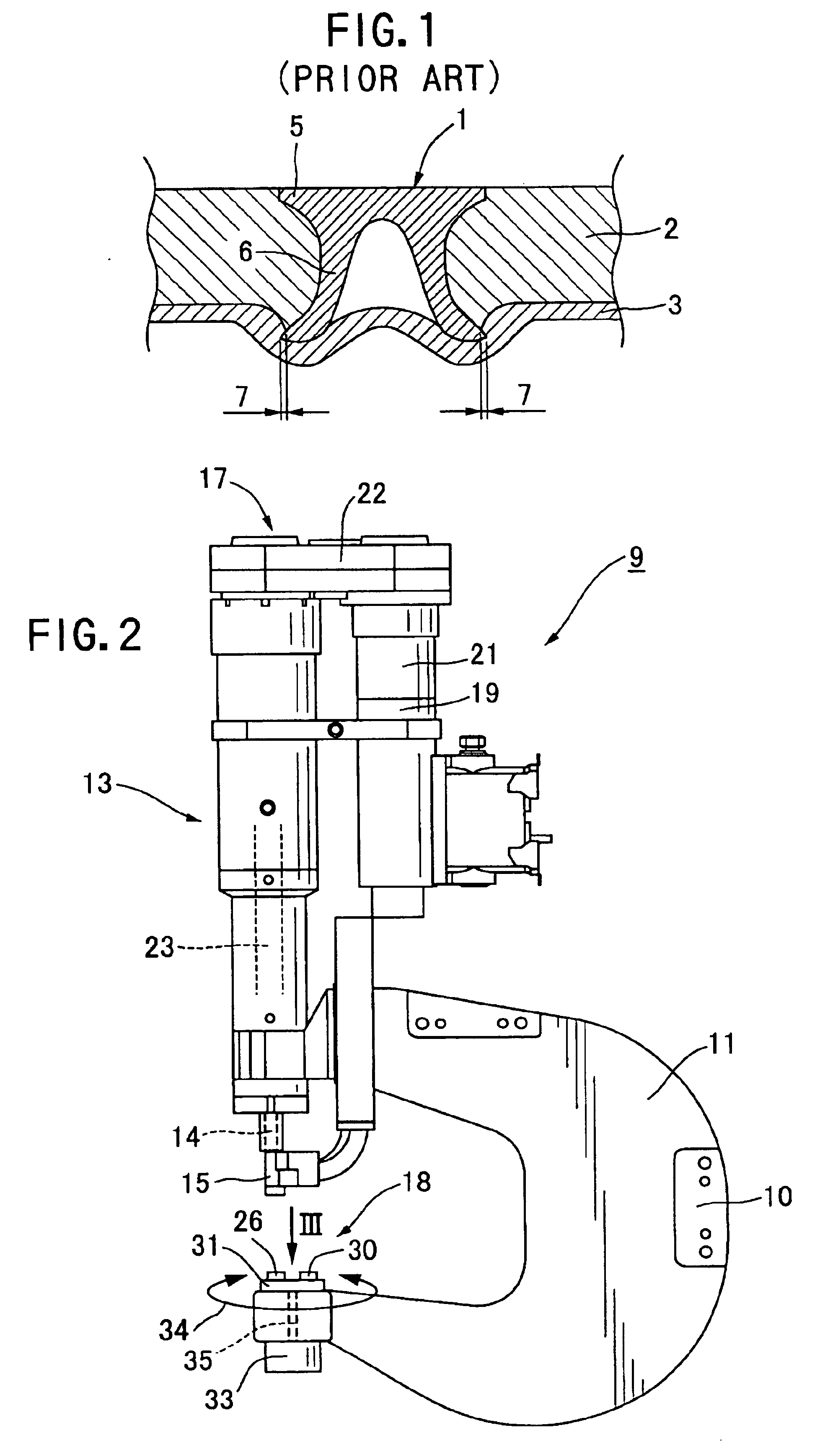
[0017]With reference to the drawings, an embodiment of the present invention will now be described. FIG. 2 schematically shows the entire structure of a self-piercing rivet setting apparatus 9 according one embodiment of the present invention. In FIG. 2, the self-piercing rivet setting apparatus 9 includes a C-shaped frame 11 having a coupling portion 10 to be coupled with an articulated robot arm (not shown). The C-shaped frame 3 is an integral rigid body including an upper horizontal arm, a vertical arm having the coupling portion 10 attached thereto, and a lower horizontal arm. A rivet setting assembly 13 of the self-piercing rivet setting apparatus is attached to or one of the ends or the end of the upper horizontal arm of the C-shaped frame 11. The setting assembly 13 is provided with a punch 14 movably attached to the front-end (the lower end in FIG. 2) thereof. A receiver unit 15 extends from the punch 14 to the front-end side. A self-piercing rivet (see the self-piercing riv...


PUM

PropertyMeasurementUnit
diameteraaaaaaaaaa
piercing depthaaaaaaaaaa
weightaaaaaaaaaa

Abstract

A self-piercing rivet setting apparatus (9) comprises a punch (14) and a die (18) for driving a self-piercing rivet into a plurality of workpieces including a receiving-side workpiece adjacent to the die. The self-piercing rivet has a large-diameter head and a hollowed leg. The leg is driven to pierce the workpieces while allowing the front end of the leg to be expanded and deformed in its radial outward direction and to be stayed in the receiving-side workpiece without passing therethrough, to connect the plurality of workpieces with each other by the expanded leg and the head. The die includes a first die member (26) having a first cavity (25), and a second die member (30) having a second cavity (27) and a protruding pin (29) provided at the center of the second cavity. The first cavity is adapted to allow the leg of the self-piercing to be driven into the workpieces in a straight direction when the self-piercing rivet is pressed by the punch (14). The second cavity and the protruding pin are adapted to allow the leg of the self-piercing rivet being piercing the workpieces to be expanded and deformed in its radial outward direction.

Description

CROSS REFERENCE TO OTHER APPLICATIONS[0001]The present application is a continuation of pending international patent application PCT / US02 / 39910, filed Dec. 13, 2002 which designates the United States, and which claims priority of Japanese patent application 2001-391576, filed Dec. 25, 2001.FIELD OF THE INVENTION[0002]The present invention relates to a self-piercing rivet setting apparatus for setting, into a plurality of workpieces, a self-piercing rivet having a large-diameter head and a hollowed leg extending from the head. More specifically, the present invention relates to the self-piercing rivet setting apparatus for connecting a plurality of workpieces, such as two or more panels (or a panel and a component), by using a self-piercing rivet in a sheet-metal assembly operation such as automobile assembling (particularly, an aluminum body assembly operation).[0003]One example of a self-piercing rivet setting apparatus is described in Japanese Patent Laid-Open No. 08-505087. FIG. ...

Claims


Application Information

Patent Timeline
Patent Type & Authority Patents(United States)
IPC IPC(8): B21J15/00B21J15/38B21J15/36B21J15/02
CPCB21J15/025B21J15/36B21J15/38Y10T29/49837Y10T29/53065Y10T29/49956Y10T29/5343Y10T29/5377Y10T29/49943Y10T29/53422
Inventor NAITO, NOBUHARU
Owner NEWFREY
Why Eureka
Try Eureka