Noise reducing silencer with spiral chambers for a compressor

a noise reduction and compressor technology, applied in the field of compressors, can solve the problems of reducing the efficiency of the compressor, noise generation at noise emitted from the air inlet or suction side of the reciprocating compressor, etc., to reduce the restriction of the inlet air flow, reduce the cost, and eliminate the effect of noise reduction

Pending Publication Date: 2020-02-13
QUINCY COMPRESSOR
View PDF3 Cites 2 Cited by
  • Summary
  • Abstract
  • Description
  • Claims
  • Application Information

AI Technical Summary

Benefits of technology

[0007]The present invention is provided to solve the deficiencies of the prior art by providing improvements over the prior art in several ways. For example, it is an object of the present invention to provide a silencer that costs less, is much smaller, and can be attached directly to the compressor air inlet to reduce or eliminate restriction to the inlet air flow.
[0008]In order to achieve the objectives of the present invention, a noise reducing silencer is provided that is attached directly to the compressor air inlet of a compressor. The noise reducing silencer has a silencer core which reduces and / or eliminates the noise at the air inlet to provide a quieter compressor without adding significant extra costs and without significantly reducing efficiency. In one embodiment of the invention, the silencer comprises a housing, a silencer core, where the silencer core comprises two spiral chambers that are stacked on each other. In another embodiment, the two spiral chambers comprise hollow walls forming the spiral chambers, where the hollow walls comprise sound absorbing material. In order to reduce costs and size, the noise reducing silencer can be incorporated into a conventional air filter for a compressor and / or include filtering elements. The noise reducing silencer may be attached directly to the compressor intake / air inlet. The noise reducing silencer can also be attached to the air filter as a separate element.
[0009]The spiral chambers can be made of metal, plastic, a composite material, or a combination thereof or include material to dampen the noise.

Problems solved by technology

During the compression process, due to the large volume of air provided through the air inlet of the compressor, noise is generated at the air inlet or suction side.
However, during operation of the reciprocating compressor, noise is emitted from the air inlet or suction side of the reciprocating compressor when the air is drawn through the inlet manifold, e.g., due to the turbulence of the air moved through the inlet.
For example, one conventional structure draws the inlet air through a large, bulky, and remotely mounted baffling box, where such structure is costly and restricts the inlet air flow by employing a long tube that connects the suction side or air inlet of the compressor to the large baffling box, which reduces the efficiency of the compressor.

Method used


Image

  • Noise reducing silencer with spiral chambers for a compressor
  • Noise reducing silencer with spiral chambers for a compressor
  • Noise reducing silencer with spiral chambers for a compressor

Examples


first embodiment

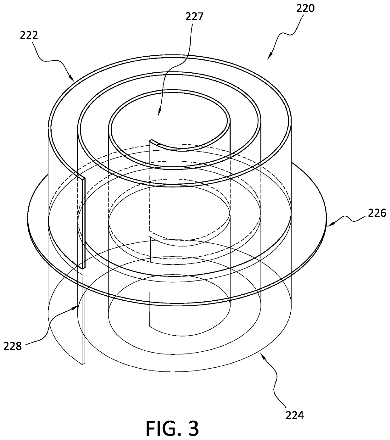
[0041]FIGS. 8A, 8B, 8C illustrate another embodiment of the invention, which is similar to FIGS. 7A-7C, but includes the spiral chambers constructed with double walls, where the enclosure between the double walls can be filled with sound-absorbing material. Specifically, the first spiral chamber 822 is provided with first spiral inlet 827, and second spiral chamber 824 is provided with second spiral inlet 828, as seen in FIG. 8A. As seen in FIGS. 8A and 8C, the outlet of the first spiral chamber 822 is connected to the second spiral inlet 828. The dimensions of the spiral chambers 822, 824 may be kept to a minimum and with the use of at least two spiral chambers, the silencer core 820 is configured to reduce noise and provide an increased amount of air flow into the noise reducing silencer, as in the other embodiments. Without limiting the invention by theory, similar to the first embodiment, in this embodiment, the spiral chambers 822, 824 create an extended and indirect path for t...

fourth embodiment

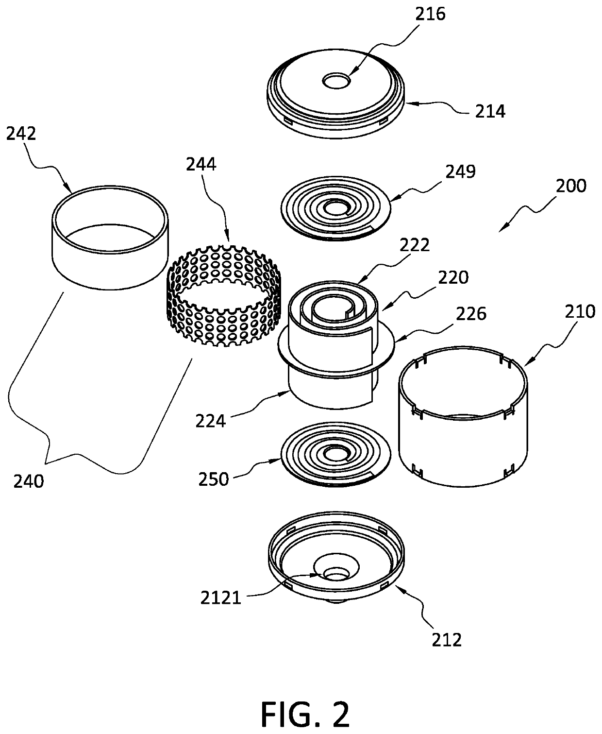
[0042]FIG. 9A illustrates a perspective cross-section view of a noise reducing silencer 900 according to the invention, which is provided with base 912 and cover 914. In this embodiment, air flows from opening 916 into first spiral chamber 922, and from first spiral chamber air outlet 931 into the second spiral chamber inlet 928, and from second spiral chamber 924, second end seal 950, and through filter 942, and then through outlet 9121 in base 912.

[0043]FIG. 9B illustrates a cross-section view of the noise reducing silencer according to the fourth embodiment of the invention, which is provided with base 912 and cover 914. In this embodiment, air flows through first spiral chamber 922, and through second spiral chamber 924, and through filter 942 and filter screen 944.

[0044]In view of such structure and features, the present invention solves the deficiencies of the prior art by providing a noise reducing silencer for a compressor installation which includes a silencer core that is ...


PUM


Abstract

A noise reducing silencer for a compressor, the silencer including a housing, a spirally shaped silencer core provided in the housing and having an inlet and an outlet, a connecting element connected to the silencer core to connect the outlet of the silencer core to an inlet of a compressor. The silencer core is provided to reduce noise during operation of the compressor, where the silencer core can include two spiral chambers stacked on each other. The spiral chambers can also include hollow walls that form the spiral chambers and that are filled with sound absorbing material.

Description

CROSS REFERENCE OF RELATED APPLICATIONS[0001]This application claims priority to provisional application No. 62 / 717,175, filed Aug. 10, 2018, and provisional application No. 62 / 719,726, filed Aug. 20, 2018, which are incorporated herein by reference.FIELD OF THE INVENTION[0002]The present invention relates generally to a compressor, and more particularly to a silencer for reducing the noise emitted from certain compressors, especially reciprocating compressors or piston compressors.BACKGROUND[0003]Compressors typically include a motor that drives a compressor element to pressurize air. The compressor element can be a reciprocating compressor or piston compressor, a centrifugal compressor, a scroll compressor, a screw compressor having male and female compressor elements, or the like. All such compressor elements have a suction side for receiving inlet air, e.g., through an inlet air filter, and an outlet side for discharging the compressed air to a tank and / or distribution header fo...

Claims


Application Information

Patent Timeline
Patent Type & Authority Applications(United States)
IPC IPC(8): F04B53/00F04B35/04
CPCF04B53/004F04B35/04F04B39/0061F04B39/005F04B39/16F04C29/065F04C18/16F04C18/0215F04C29/063
Inventor REN, TINGRONGCENTERS, STEVEKALAPOS, GERALDWALKER, BYRONBACCIN, ERIK
Owner QUINCY COMPRESSOR
Why Eureka
Try Eureka