Collection container assembly

Inactive Publication Date: 2005-06-28
BECTON DICKINSON & CO
View PDF18 Cites 68 Cited by
  • Summary
  • Abstract
  • Description
  • Claims
  • Application Information

AI Technical Summary

Benefits of technology

[0012]The cylindrically generated outer surface of the inner tube may be roughened to define an array of peaks and valleys. The maximum diameter defined by the peaks may be equal to or slightly greater than the inside diameter of the outer tube. Hence, the peaks on the roughened cylindrically generated outer surface of the flared top on the inner tube will provide secure engagement between the inner and outer tubes. However, the valleys between the peaks on the roughened cylindrically generated outer surface at the top of the inner tube will define circuitous paths for venting air trapped in the circumferential space between the inner and outer tubes at locations between the flared top of the inner tube and the closed bottom of the outer tube and to prevent liquid from entering the circumferential space between the inner and outer tubes. Liquid is prevented from entering the space between the inner and outer tubes because due to the pore size, viscosity and surface tension of the liquid. As a result, the container assembly achieves efficient nesting without longitudinal grooves and close dimensional tolerances and simultaneously enables evacuation of air from the space between the inner and outer tubes so that a vacuum condition can be maintained within the inner tube for an acceptably long time and prevents liquid from entering the space between the inner and outer tubes.

Problems solved by technology

Therefore, it is difficult to maintain the shelf-life of plastic tubes that contain a liquid additive.
It is also appreciated that deterioration of the volume and concentration of the liquid additive may interfere with the intended use of the tube.
Furthermore, air trapped between the two closely fitting nestable containers can complicate or prevent complete nesting.
However, the grooves complicate the respective structures and the grooved containers still require close dimensional tolerances.
This approach, however, complicates and lengthens an otherwise efficient manufacturing cycle.

Method used


Image

  • Collection container assembly
  • Collection container assembly
  • Collection container assembly

Examples


Embodiment Construction

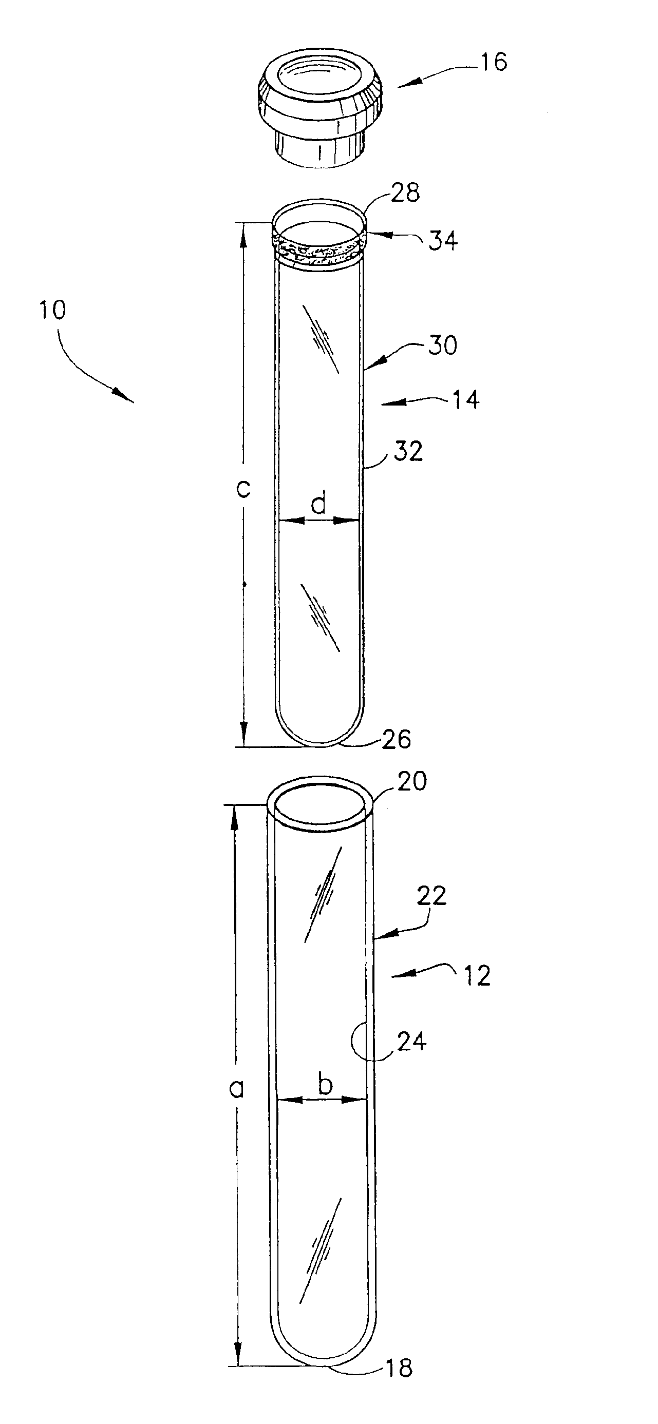
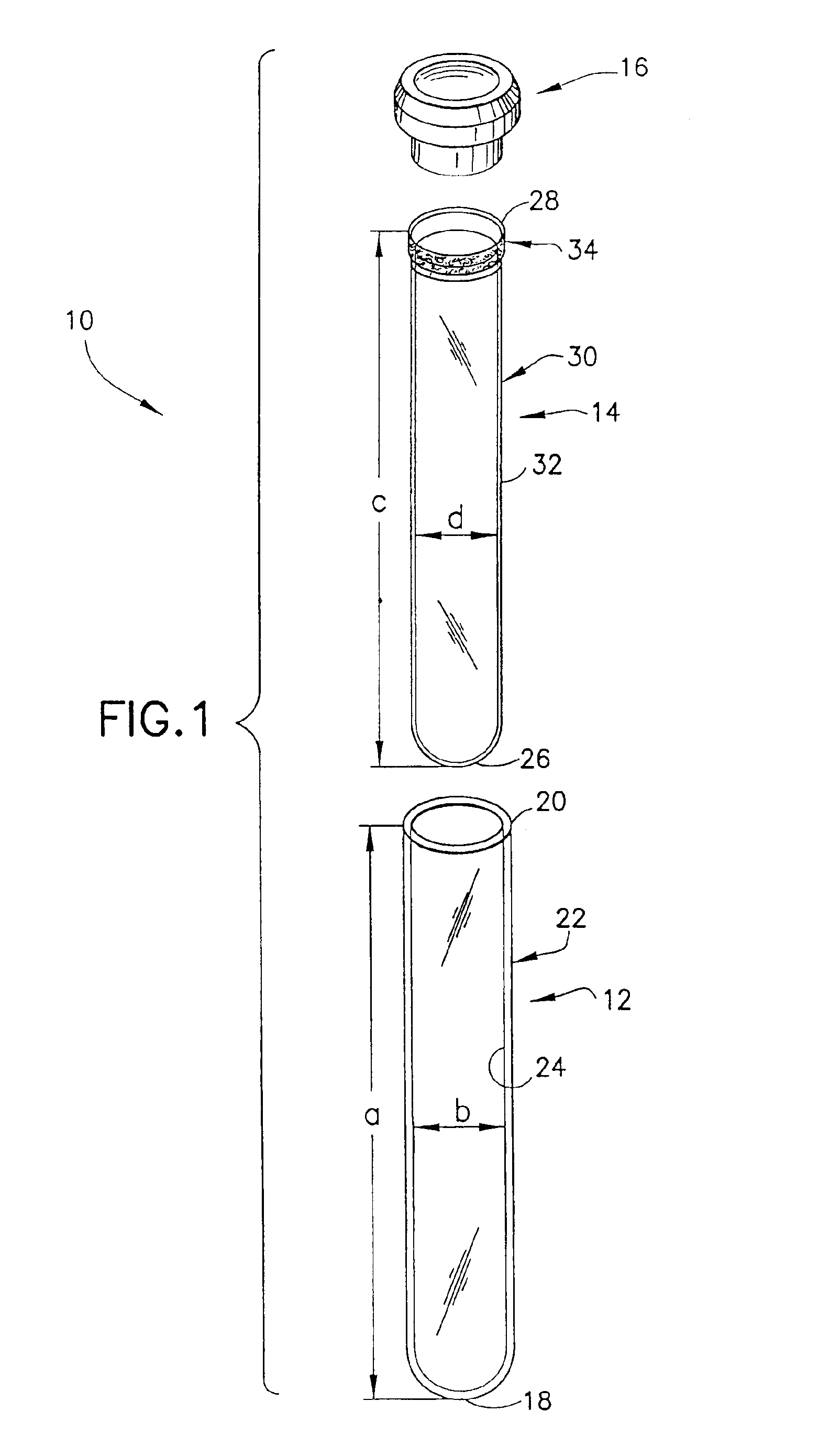
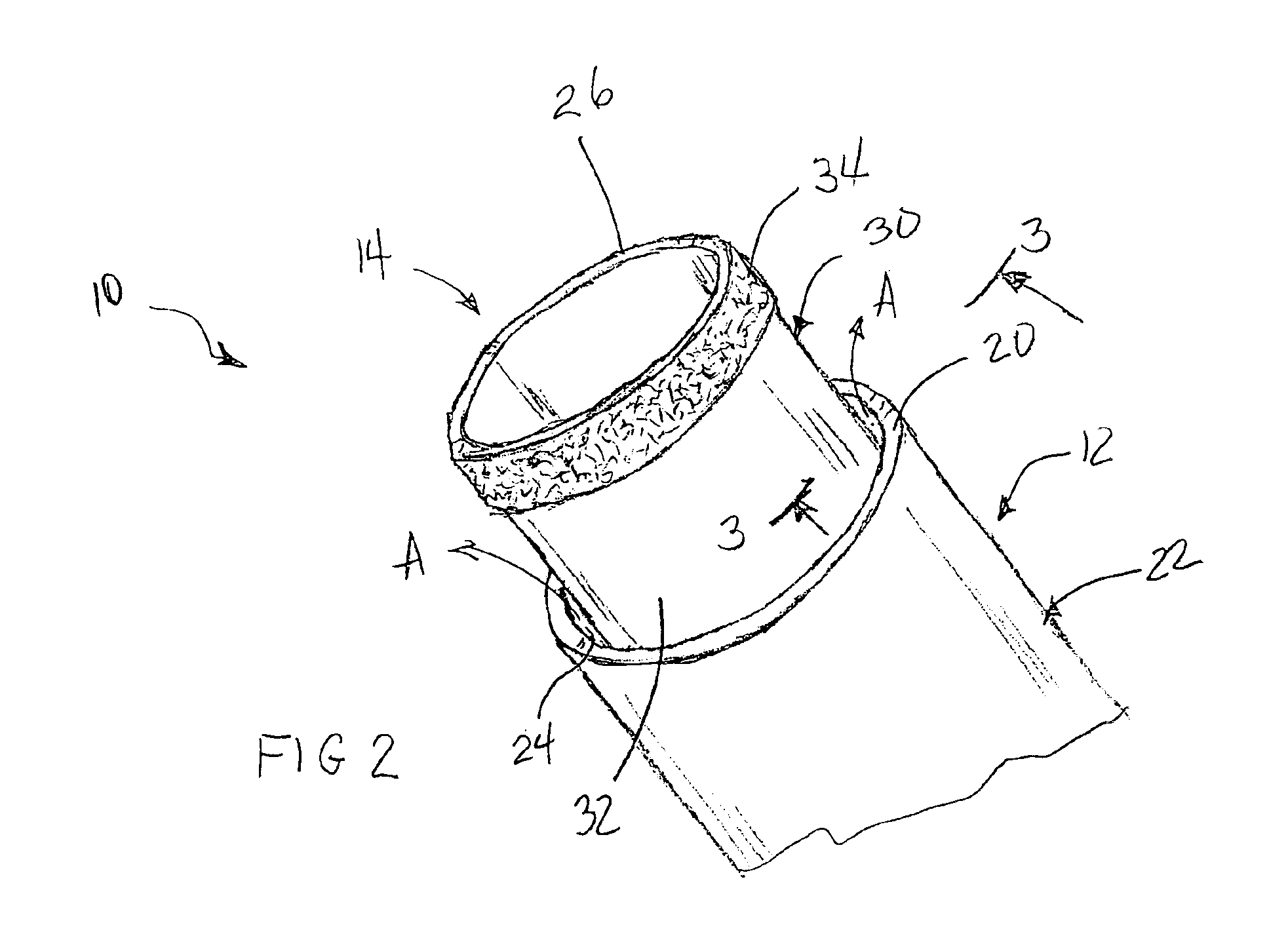
[0019]As shown in FIGS. 1-6, an assembly 10 includes an outer tube 12, an inner tube 14 and a closure 16.

[0020]Outer tube 12 is unitarily formed from PET and includes a spherically generated closed bottom wall 18, an open top 20 and a cylindrical wall 22 extending therebetween whereby side wall 22 slightly tapers from open top 20 to closed bottom wall 18. Outer tube 12 defines a length “a” from the interior of the bottom wall 18 to the open top 20. Side wall 22 of outer tube 12 includes a cylindrically generated inner surface 24 with an inside diameter “b”.

[0021]Inner tube 14 is unitarily formed from polypropylene and includes a spherically generated closed bottom wall 26, an open top 28 and a cylindrical side wall 30 extending therebetween whereby side wall 30 slightly tapers from open top 28 to closed bottom wall 26. Inner tube 14 defines an external length “c” that is less than internal length “a” of outer tube 12. Side wall 30 of outer tube 14 includes a cylindrical section 32 e...


PUM


Abstract

The present invention is a container assembly that includes an inner tube formed from a plastic that is substantially inert to bodily fluids and an outer tube that is formed from a different plastic. Collectively, the container assembly is useful for providing an effective barrier against gas and water permeability in the assembly and for extending the shelf-life of the container assembly, especially when used for blood collection. The inner container is spaced from the outer container at most locations. However, the inner container includes an enlarged top configured to engage the outer container. The enlarged top has a roughened outer surface to permit an escape of air from the space between the containers.

Description

RELATED APPLICATIONS[0001]This application is a divisional application of Ser. No. 09 / 933,653 filed on Aug. 21, 2001 now U.S. Pat. No. 6,651,835, which is a continuation in part of Ser. No. 09 / 625,287 filed on Jul. 25, 2000, now U.S. Pat. No. 6,354,452.BACKGROUND OF THE INVENTION[0002]1. Field of the Invention[0003]The invention relates to a collection container assembly that includes a plurality of nested containers formed from different respective materials and provides an effective barrier against water and gas permeability and for extending the shelf-life of assembly especially when used for blood collection.[0004]2. Description of the Related Art[0005]Plastic tubes contain an inherent permeability to water transport due to the physical properties of the plastic materials used in manufacturing tubes. Therefore, it is difficult to maintain the shelf-life of plastic tubes that contain a liquid additive. It is also appreciated that deterioration of the volume and concentration of t...

Claims


Application Information

Patent Timeline
IPC IPC(8): B01L3/14G01N33/48B65D1/00B65D8/06G01N1/00
CPCB01L3/5082B01L2300/10B01L2300/042B01L2200/141
Inventor ISKRA, MICHAEL
Owner BECTON DICKINSON & CO
Why Eureka
Try Eureka