Articulated headrestraint system

a headrest and articulation technology, applied in the field of articulation headrest systems, can solve the problems of dependencies of the movement of the headres

Inactive Publication Date: 2005-06-28
CAMACO
View PDF10 Cites 47 Cited by
  • Summary
  • Abstract
  • Description
  • Claims
  • Application Information

AI Technical Summary

Benefits of technology

[0002]For a number of years the sole purpose of vehicle headrests was for the comfort of the occupant. The headrest could be adjusted up and down in most cases, and moved fore and aft in some expensive models. A typical headrest consists of a notched rod that may be straight or bent in a “U” shape and held in the car seat's guide tube. Foam and trim covers are placed on top of the rod (the headrest assembly) to give head and neck support and passenger comfort. The notches placed along the length of the rod help in moving the headrest assembly up and down, and locking the headrest in a specific place depending upon the occupant's height.
[0006]The present invention provides a head restraint system that overcomes some of the above-described problems of the related art. The invention allows the occupant to lock the headrest in a specific position. The headrest can be moved forward with minimal effort, while moving the headrest in the opposite direction requires a pushbutton activation. The invention also combines up and down motions and eliminates the effort issues related to seat frame dimensional tolerances.

Problems solved by technology

The problem with existing designs is that efforts to move the headrest depend upon the dimensional tolerances of seat frame components.

Method used


Image

  • Articulated headrestraint system
  • Articulated headrestraint system
  • Articulated headrestraint system

Examples


Embodiment Construction

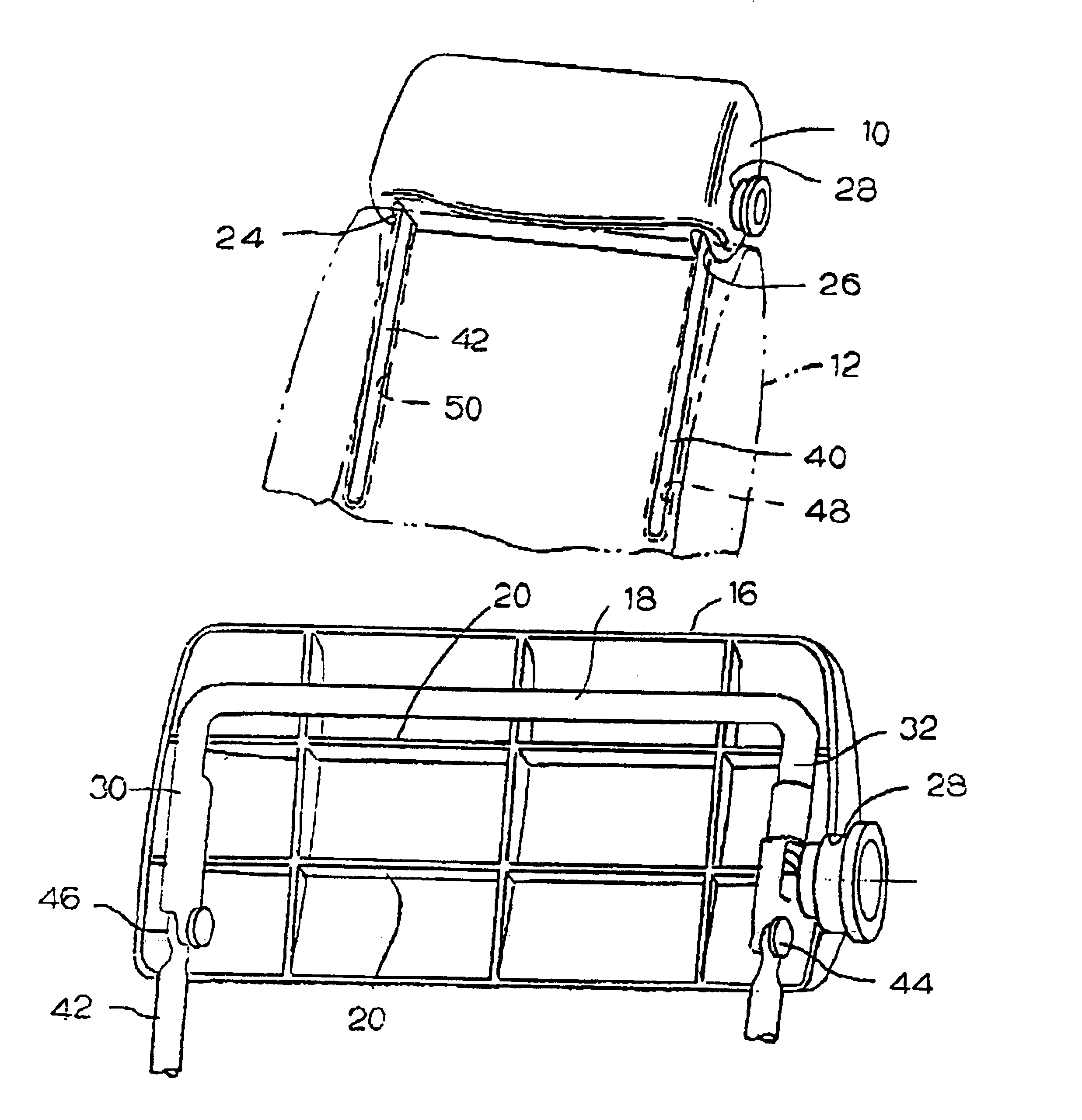
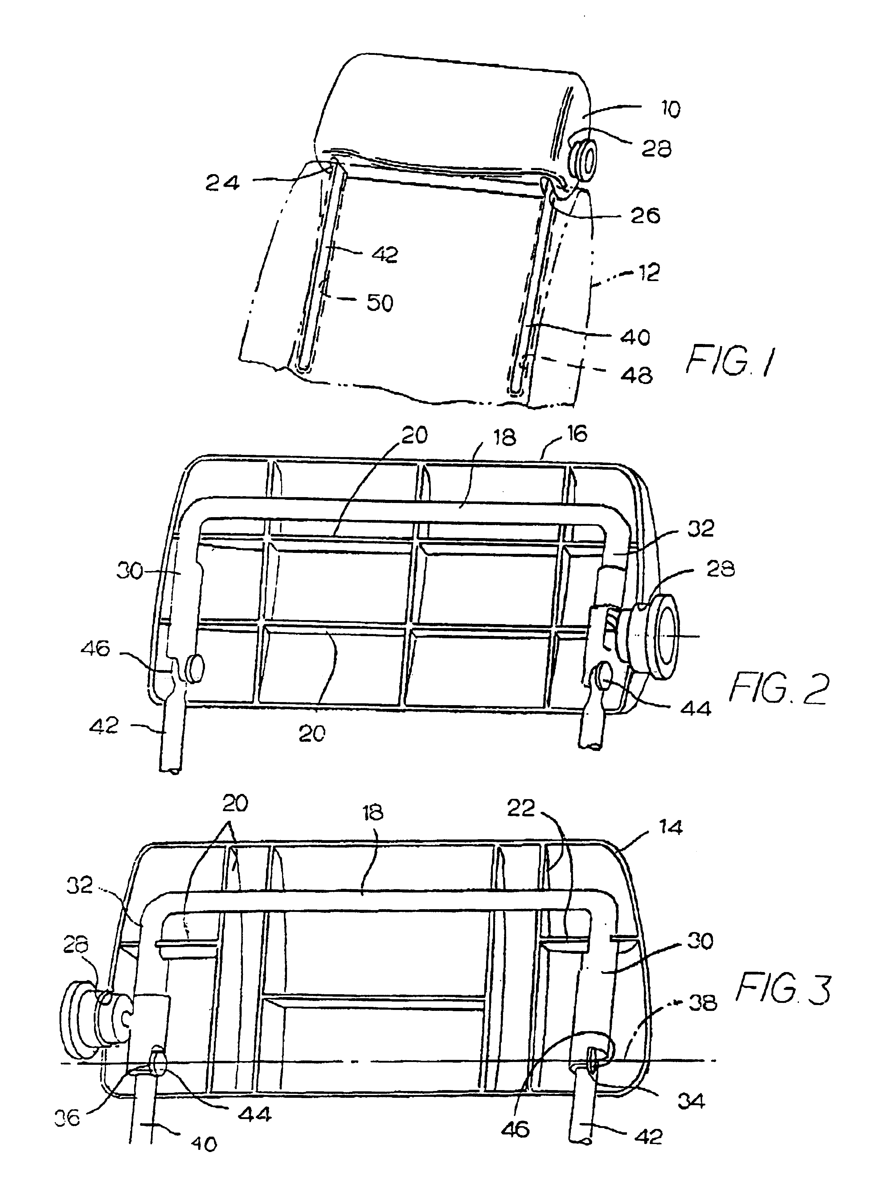
[0024]Referring to the drawings, FIG. 1 illustrates an adjustable headrest 10 mounted on a vehicle seat back 12, illustrated in phantom. Referring to FIGS. 2 and 3, headrest 10 includes a back cover 14 fastened to a front cover 16. The two covers have edges formed together to form a hollow headrest housing. A U-shaped tubular upper support member 18 is captured between the front and rear covers in ridge means 20 and 22, respectively. When the two covers are joined together, they combine to form a pair of lower slots 24 and 26. The two covers also combine to form a side button opening 28. Support member 18 is fixed to and moves with the two covers.

[0025]Support member 18 has a pair of parallel brackets 30 and 32. The lower ends of the two brackets have rivet-receiving openings 34 and 36, aligned along a pivotal axis 38.

[0026]A pair of upright parallel legs 40 and 42 have upper flattened ends connected by rivet means 44 and 46 to the lower ends of brackets 32 and 30, respectively. The...


PUM


Abstract

An articulated headrestraint system for a vehicle seat permits the user to adjust the headrest vertically, and to adjust the headrest either forwardly by using a pushbuttom mechanism, or rearwardly with respect to the top of the seat.

Description

FIELD OF THE INVENTION[0001]The present invention generally relates to an Articulated Head Restraint System that is part of an automobile.BACKGROUND AND SUMMARY OF THE INVENTION[0002]For a number of years the sole purpose of vehicle headrests was for the comfort of the occupant. The headrest could be adjusted up and down in most cases, and moved fore and aft in some expensive models. A typical headrest consists of a notched rod that may be straight or bent in a “U” shape and held in the car seat's guide tube. Foam and trim covers are placed on top of the rod (the headrest assembly) to give head and neck support and passenger comfort. The notches placed along the length of the rod help in moving the headrest assembly up and down, and locking the headrest in a specific place depending upon the occupant's height.[0003]The headrests that move fore and aft are typically of a riveted design (4-way). The headrest is made in two parts. The upper section has welded brackets and a pair of not...

Claims


Application Information

Patent Timeline
Patent Type & Authority Patents(United States)
IPC IPC(8): B60N2/48
CPCB60N2/4844B60N2/4814B60N2/815B60N2/844
Inventor BAKER, CHRISTOPHERBHANDARI, AJAY
Owner CAMACO
Why Eureka
Try Eureka